![]()
Installing Mini Cooper R53 Gauges
The Mini
Cooper S comes from the factory with a few gauges: speedo, tach, fuel level,
water temp (somewhat), and a few idiot lights…..but I’m not an idiot and like
to know what is going on with the car. I decided to install boost and oil
pressure gauges using the Craven mounting system on either side of the
speedometer. I purchased an oil temp gauge as well with the AC vent mount but
will wait until later to install that, maybe when I replace the oil pan and can
get it tapped for the sender.
The ALTA boost gauge installation
instructions were VERY helpful in locating power, ground, ignition, and
boost sources. I had to feel my way through the oil pressure sender
installation but found a few threads on
Craven X
Mounting Bracket Installation instructions are HERE,
Gauge Cup Mounting instructions are HERE.
AutoMeter Electric Pressure Gauge
Installation instructions are HERE,
Mechanical Boost Gauge Installation instructions are HERE,
Electric
Boost Gauge Installation instructions are HERE.
Standard
Disclaimer: ANY USE OF THIS INFORMATION
BY YOU IS AT YOUR OWN RISK. I ASSUME NO LIABILITY FOR YOUR USE OF THE BELOW
INFORMATION.

Oil Pressure Gauge Sender
Installation:
First step
is to source a gauge and an adapter. I went with the Cravenspeed Adapter
(CRMC-0024, http://www.cravenspeed.com/products/Gauge-Sender-Adapters.html)
and Autometer 4352 Full Sweep Electric 1-100 PSI gauge (http://www.autometer.com/cat_gaugedetail.aspx?gid=3781&sid=11).
I had heard that mounting the electric sender to the engine would kill the
sender quickly….and I found out it does so I ordered the AMS Remote Oil
Pressure Sending Unit Line (http://www.amsperformance.com/cart/AMS-Remote-Oil-Pressure-Sending-Unit-Line.html)
and remotely mounted the sender to the fender.
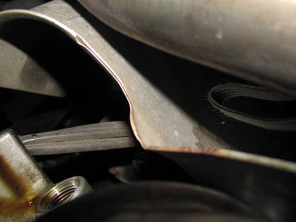
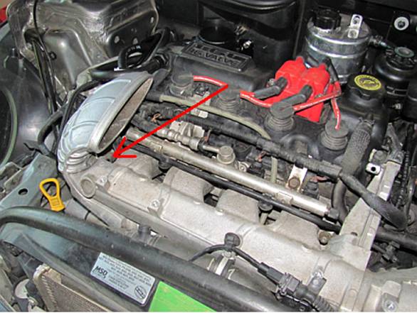
I had to
remove some things to access the stock sender location under the oil filter:
strut bar, oil catch can, M7 Aerogel, and the OE heat shield. The heat shield
is removed by removing two bolts using a 13mm wrench; the other heat shield can
be carefully bent up and out of the way:
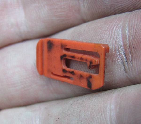
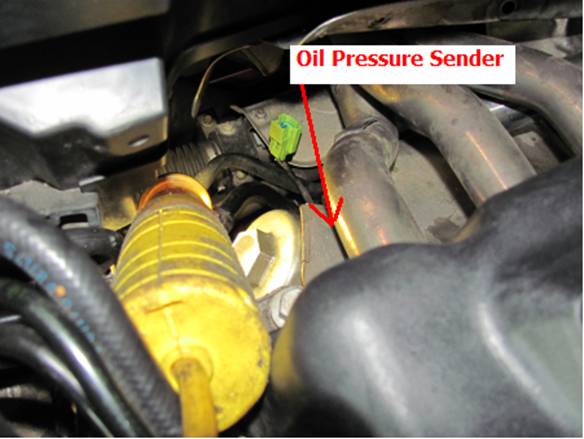
If you
look/feel to the right and slightly below the oil filter you will find the OE
oil pressure sender. The plug can be removed after removing the red plastic
locking clip pictured by pressing the release tab and pulling:
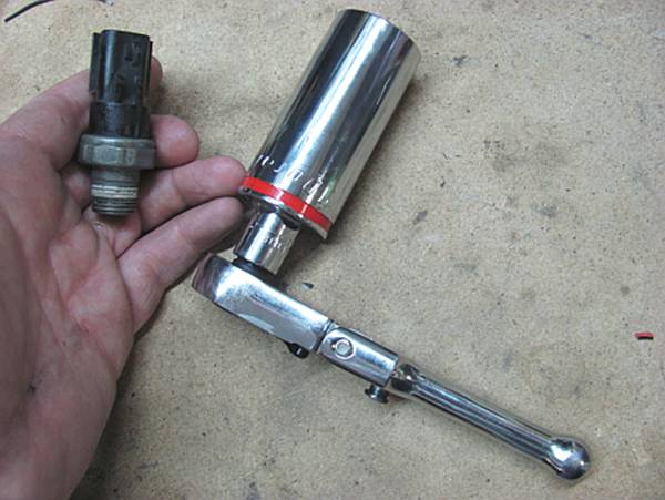
You will
need a deep 27 mm socket, preferably a six point, to remove the OE sender.
Since this large socket is commonly found for ½” wrenches, I used a 3/8” to
1/2" adapter and a short 3/8” wrench- there is not a lot of room to move
(or take pictures):
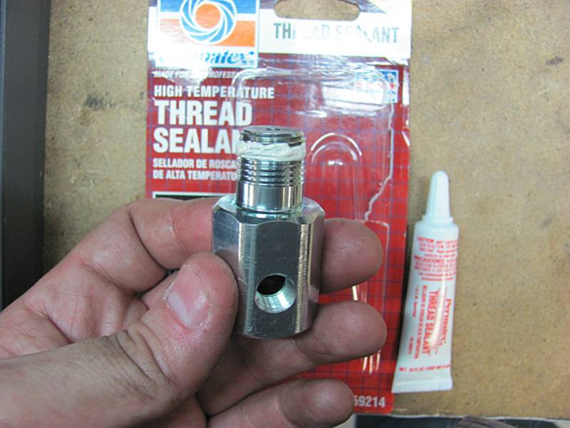
I have
used Teflon tape in the past but decided to use thread sealant for this
project. Be careful to follow the directions and only apply after the first
couple of threads- the adapter and sender/extension have to ground for the
senders to work. Sealant was used on ALL connections:
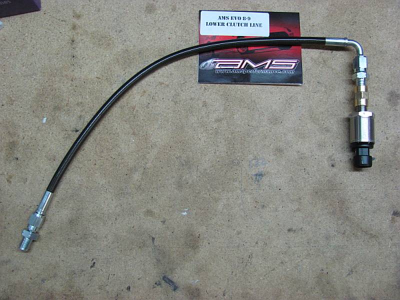
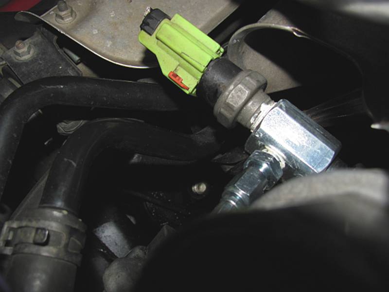
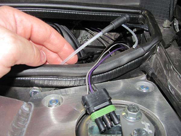
Remote
line with new electric gauge sender attached, the vendor I ordered from sent me
the more expensive clutch line instead of the remote line I had ordered so I
had to source a 1/8 NPT female>female adapter for the sender side of the
line, again sealant used on all connections:
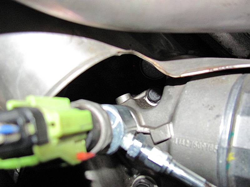
The same
27mm deep socket can be used to install the Cravenspeed adapter where the OE
sender was removed. The OE sender is reinstalled on the end of the adapter, the
remote line is installed on the side port of the adapter. Be sure to note where
this side port is so as you tighten it will be indexed in a position that is
optimal for your sender or remote line.
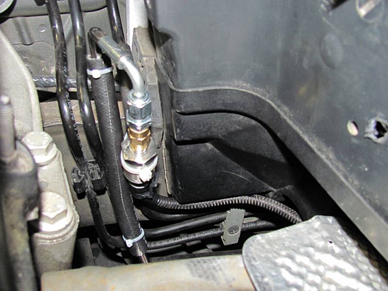
The remote line was run to the passenger side fender and zip tied to one of the
OE lines. I used some rubber heater hose to prevent the line from rubbing any
of the lines or mounts, make sure there is some slack to account for engine
movement. The sender wiring was loomed and run through a hole drilled (and
rubber grommet installed) in the bottom of the fresh air duct- not necessary to
be here if you use the remote mount method, my hole was here when I originally
mounted the sensor to the motor and the logistics made sense. This line was run
over to the brake booster area so that it could be run into the car- that is
covered later in this write-up after the boost gauge installation.
Boost Line Installation:
The ALTA boost gauge installation instructions
were VERY helpful in locating power, ground, ignition, and boost sources.
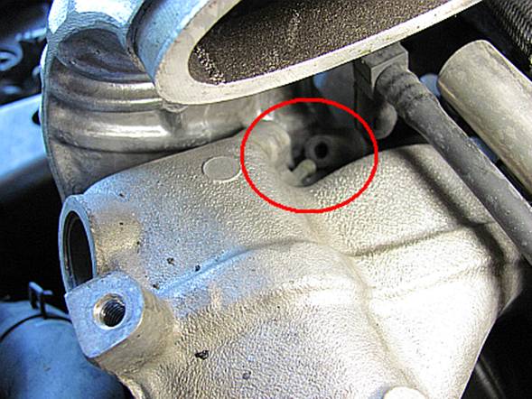
While I
had the OE intercooler out to install my new DOS intercooler, I installed the
boost line. It can be done with the intercooler in place using the Alta
instructions, but is SUPER easy when it’s out. Looking to the left/passenger
side of the intercooler and towards the front, you will see where the fuel
pressure regulator is connected (mine has already been disconnected in the pics
below):
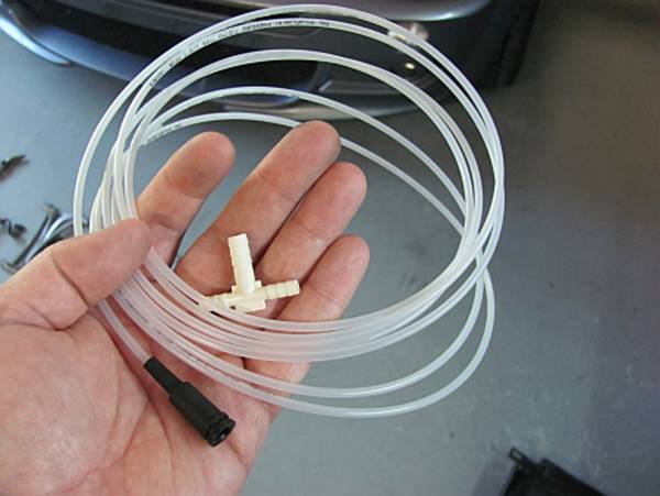
The provided line that came with your gauge (hopefully, if not kits are
available) has a plastic T and a rubber adapter. The factory line is unplugged
from the intake. A short piece of vacuum line is attached to one barb, the new
line attached to one barb, and the OE line attached to one barb. I found the OE
line to be a bit loose so I used a zip tie to clamp it down tight. After the T
is connected to the boost lines it is reconnected to the intake. You may need
to trim the length of the vacuum line used to minimize contact and rubbing of
the two vacuum lines:

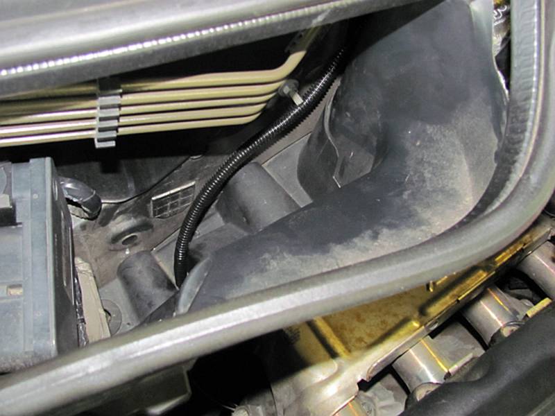
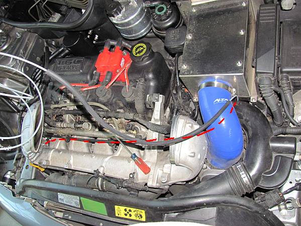
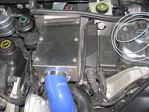
The boost
line is carefully run under the intake manifold runners and air intake
hose/tube and then up and out at the airbox. It was then run between the airbox
and ECU, through an available hole, and underneath the brake fluid reservoir. I
chose to slide vacuum line over the boost line for protection AND to keep it
somewhat camouflaged:
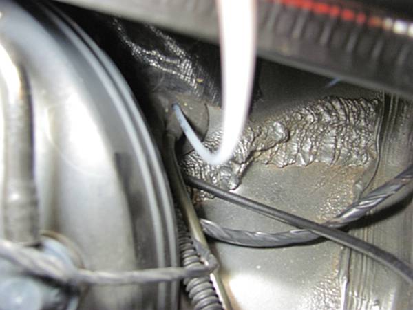
Running Boost Line and Wiring into
the Car:
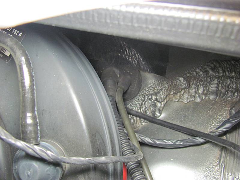
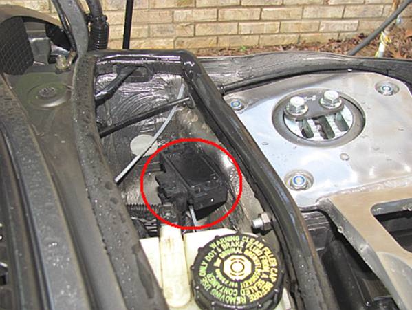
The rubber
grommet behind the brake booster is where the line and wires will be run into the
car:
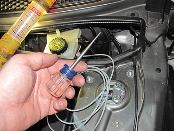
I used an
awl to poke a hole through the grommet, be careful not to puncture anything
other than the grommet:
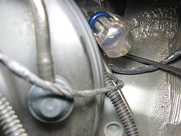
Since the
boost line more rigid than the wiring, I inserted that in the hole first.
Wiring can be attached to the line using black electrical tape and they can be
pulled through together. If you are not installing a boost gauge, baling wire
or an old metal coat hanger can be used to feed the wiring in.
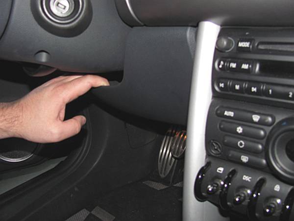
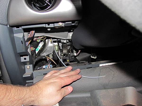
Back
inside the car the firewall entry point can be accessed by dropping the under
dash panel- put hands in space under steering column and push/pull down. It
will unsnap from the dash and tilt down on hinges:
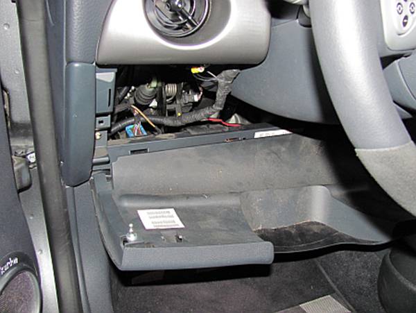
Find the
place where the line is coming in and slowly pull it in, it is nice to have a
helper on the outside let you know when there is no more line left to pull in:
Installing the Gauges (and
Replacing the Mechanical Boost Gauge with an Electric Boost Gauge):
I am not
going to provide a lot of additional detail here since it is covered by other
existing sources and the manufacturer instructions. I will note that there is
no easy way to route the AutoMeter gauge harness through the firewall with the
connectors installed. My attempt to remove the pins was a problem so I just cut
the wiring harness in half and ran it through that way, this also allowed me to
adjust the length before crimping them back together. Using the right crimps
and the right tool can result in a wire almost as good as a solid one.
The ALTA boost gauge installation
instructions were VERY helpful in locating power, ground, ignition sources.
Read these FIRST.
CravenSpeed X Mounting Bracket
Installation instructions are HERE, Gauge
Cup Mounting instructions are HERE.
AutoMeter Electric Pressure Gauge
Installation instructions are HERE, Mechanical
Boost Gauge Installation instructions are HERE,
Electric
Boost Gauge Installation instructions are HERE.
I chose to
use the Craven Mounting System, keep in mind when ordering gauge cups that they
are metric and some gauges (Autometer) are standard sized. 2 1/16” is 52.4mm
and 2 5/8” is 66.7mm. My 2 1/16” gauges fit fine in the Craven 52mm gauge pods
but the 2 5/8” boost gauge was TIGHT in
the 66mm pod, even after lightly sanding both the inside of the pod and the
gauge perimeter itself.
I also
decided I didn’t like the 2 5/8” boost gauge so after a week it was replaced
with the 2 1/16” electric boost gauge. It is smoother in operation, is
symmetric with the other gauge, and requires less clearance when mounting. I
also does not interfere with the stalk and can be angled the same as the other
gauge.
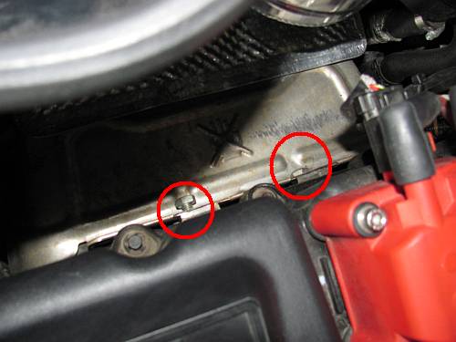
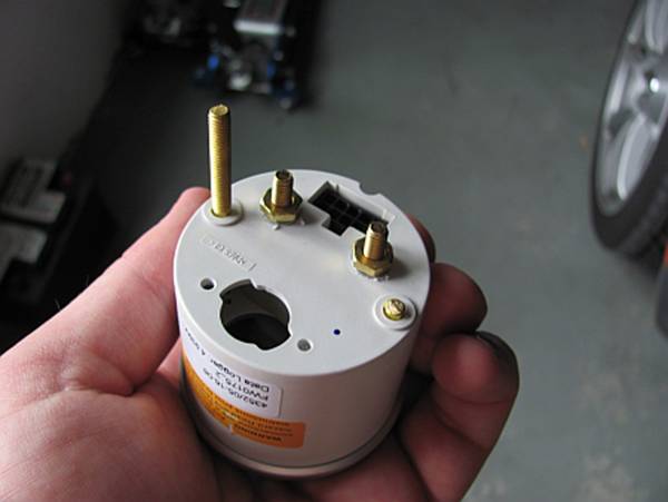
I have the
older style CravenSpeed gauge mounts with set-screws so removing the protruding
threaded studs was easy- a pair of pliers and a die grinder with cutoff wheel
were used to completely pull the studs out or cut them off. Picture below shows
one removed:
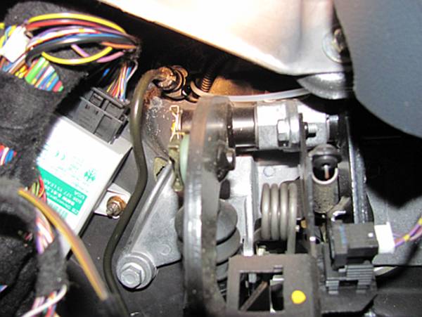
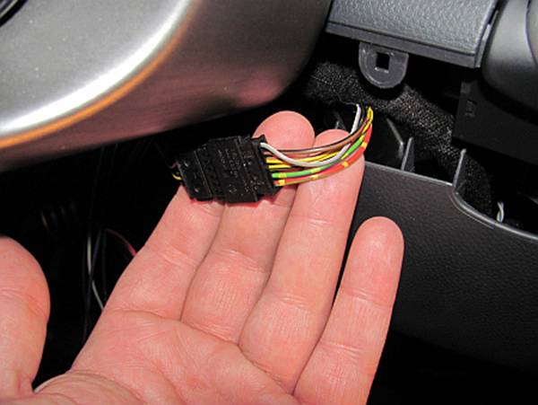
Here is a
better view of the ignition wiring source, the Alta instructions have good pics
of the ground source:
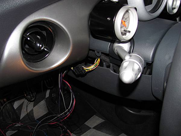
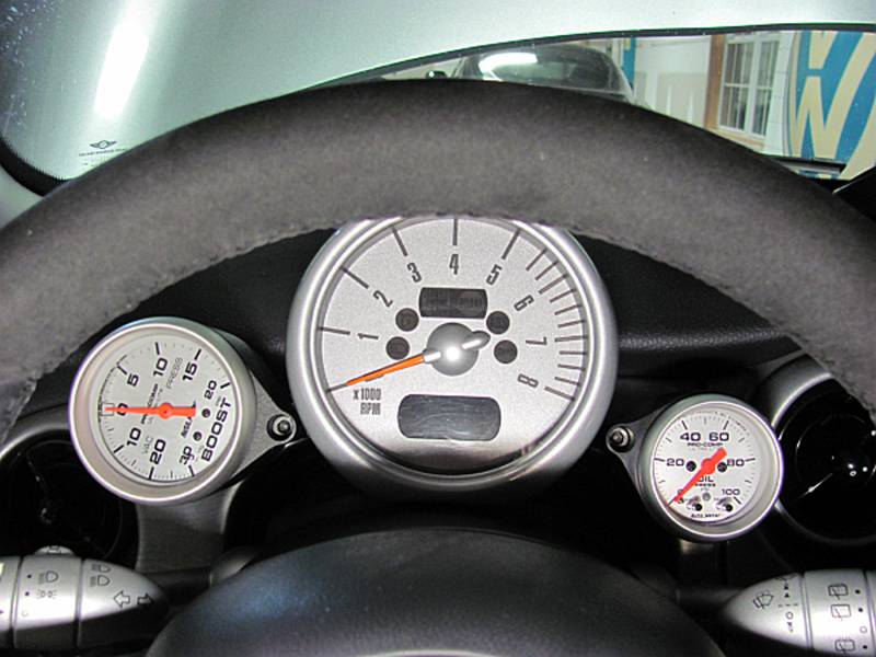
This is
the original config that lasted for a week with the 2 5/8” mechanical boost
gauge (Autometer 4401); I had it rotated for max clearance of the boost line
fittings since I did not want to use a right angle adapter or the pod spacers.
A single small hole was made in the rubber accordion boot at the top rear of
the steering column to run wires, be careful to route wires in a way that they do NOT interfere
or make contact with the steering column or pedals. I also used wiring loom inside the car to make things
neat, organized, and protected:
Installing
the new Electric Boost Gauge was fairly easy. I just cut the boost line outside
the car so I had a way to feed the new wires through. The MAP sensor was
mounted to the inside of the fresh air duct using E6000 adhesive- I LOVE this
stuff. If I ever decide to remove it I can just pull it off and peel off the
adhesive. The boost line was fitted with a rubber adapter and connected to the
map sensor. After the new wiring was pulled through the hole was sealed well
with silicone sealant, be sure to get it in between the wires as well so
capillary action doesn’t suck water in:
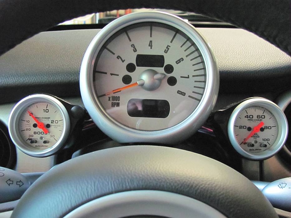
The newest
and current setup- AutoMeter Boost Gauge 4377 and Oil Pressure Gauge 4352:
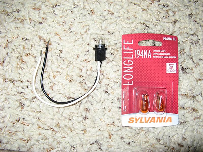
I did find
that replacing the clear bulbs with some orange bulbs AND using the AutoMeter provided
red covers was a close match to the OE gauge lighting. I have heard using a red
Sharpie to color the orange bulbs is even better, maybe I will try that next
time.