![]()
My BMW M Coupe/Z4
Subwoofer Installation
My M Coupe
came with the Top HiFi Carver system that is the first THX certified factory
stereo from a European car manufacturer. Surprisingly though, it seemed to lack
low-end, there is only so much bass you can get from 6 inch subwoofers.
BMW Z4 THX
articles here: http://www.thx.com/auto/bmw.html , http://www.thx.com/news/20060329A.html , http://www.worldcarfans.com/10603307423/bmw-z4-thx-certified
In
researching any installations of additional subwoofers to the factory system I
found a few forum posts that helped get me started, THANKS to all of these guys
for their contributions that made this project an easier start for me:
http://www.zpost.com/forums/showthread.php?t=63030&highlight=subwoofer
– GV from
http://www.bimmerfest.com/forums/showthread.php?t=200546&highlight=subwoofer - peeti’s JL 250.1 amplifier and JL 10W3v3-2 subwoofer add-on
http://www.zpost.com/forums/showthread.php?t=248228&highlight=subwoofer
- Graham M’s replacement of the Carver subwoofers and RF amplifier add-on
http://www.bimmerfest.com/forums/showthread.php?t=329901&highlight=subwoofer - withaJ’s Blaupunkt THb200A add-on
NOTE: THIS WEB PAGE IS
PROVIDED FOR INFORMATIONAL PURPOSES ONLY, USE OF ANY OF THE INFORMATION
CONTAINED IS AT USERS OWN RISK, ALL INFORMATION SHOULD BE VERIFIED FOR USER
SPECIFIC APPLICATION.
COMPONENTS:
Amplifier:
Owners
Manual, Press
Release, Comparison
to “Old” Punch 45HD, Crutchfield
Review, Factory Tour,
Website

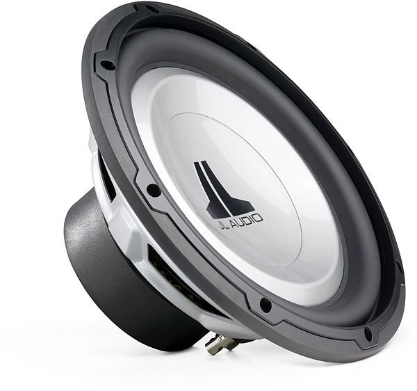
Subwoofer Speaker: JL
Audio 10W1v2-4

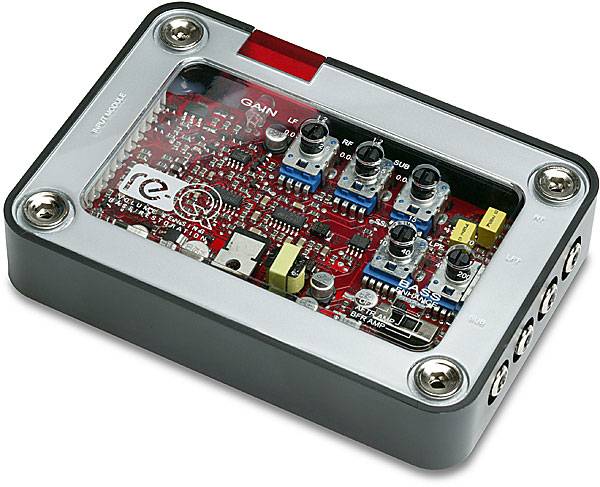
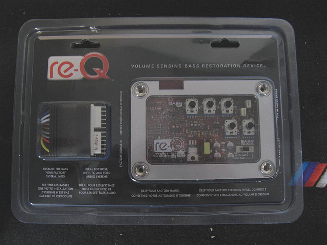
Line Level
Converter/Bass Restoration Processor: MTX REQ
Owners Manual, Performance Auto & Sound
Review, Website
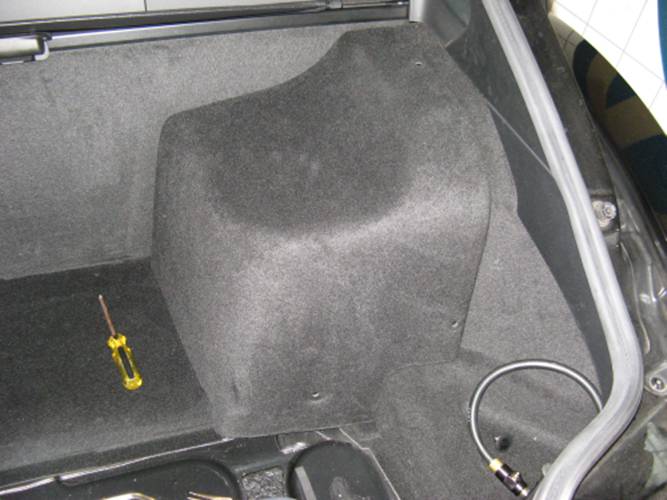
TRIM REMOVAL:
To see
where the needed wires were at, I had to disassemble the rear bulkhead panel. This
is done by first removing the battery cover (three twist clips):
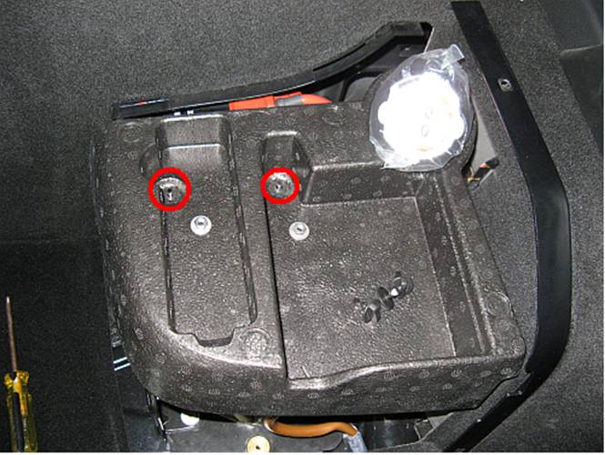
Removing
the foam holder for the tire inflation tools (removing two 10mm nuts):
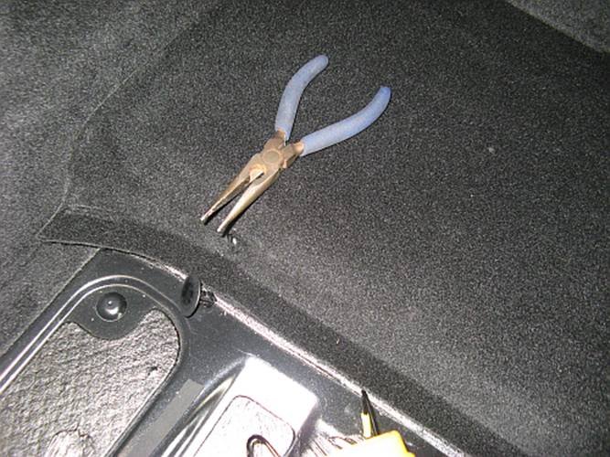
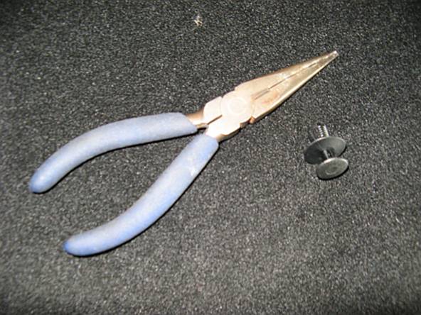
Removing
the plastic retainer from the carpet after lifting out the rear carpet piece
(easy to do using needle nose pliers on either side of the retainer and pulling
out):
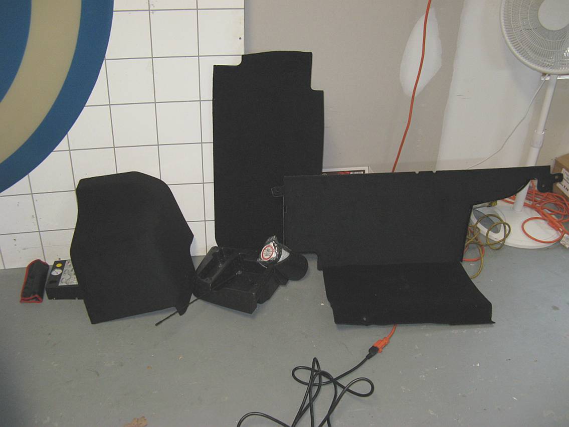
And then
removing the plastic rivets that hold the bulkhead carpet piece in. Minimally,
the passenger side retainers (two) can be removed and the piece can be
carefully flexed to the driver side. In addition the driver side retainers
(three, one rivet style behind the light and two clips holding the bulkhead
piece to the side piece) can be removed so the bulkhead cover can be removed
from the car:
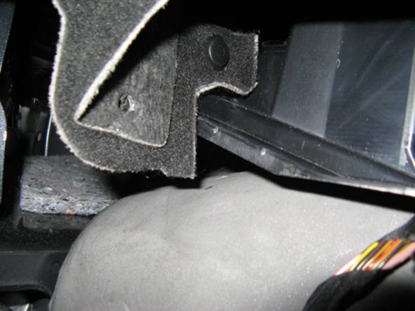
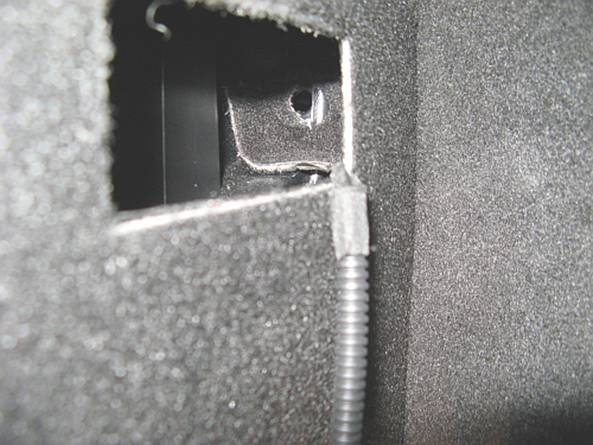
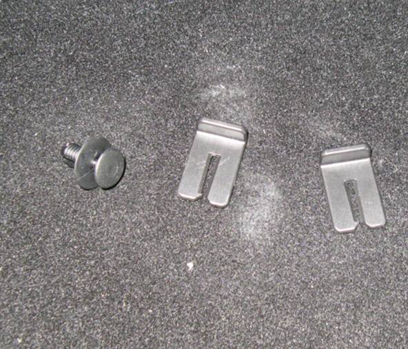
All things
removed so far, you can see the two slots on the left of the bulkhead cover
where the side pieces go through and the push on clamps pictured above hold
them together:
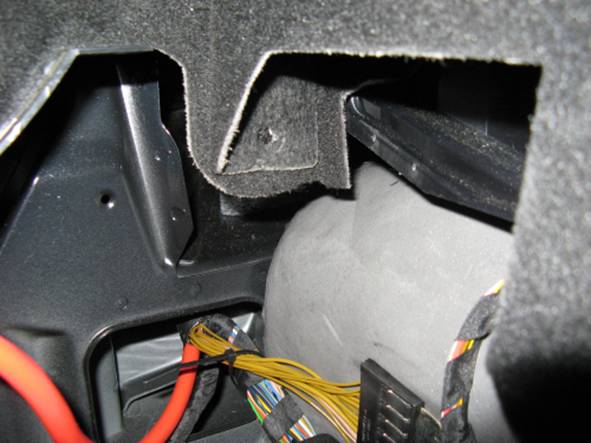
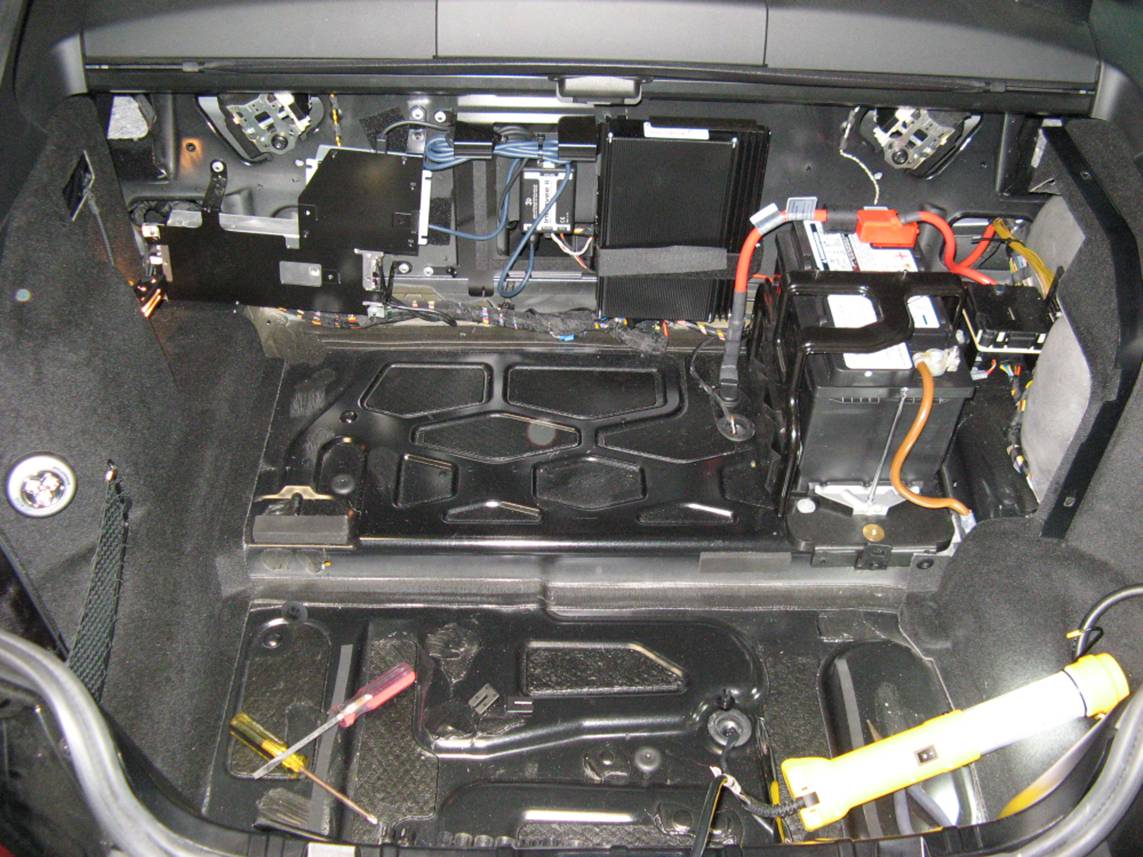
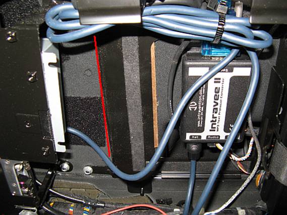
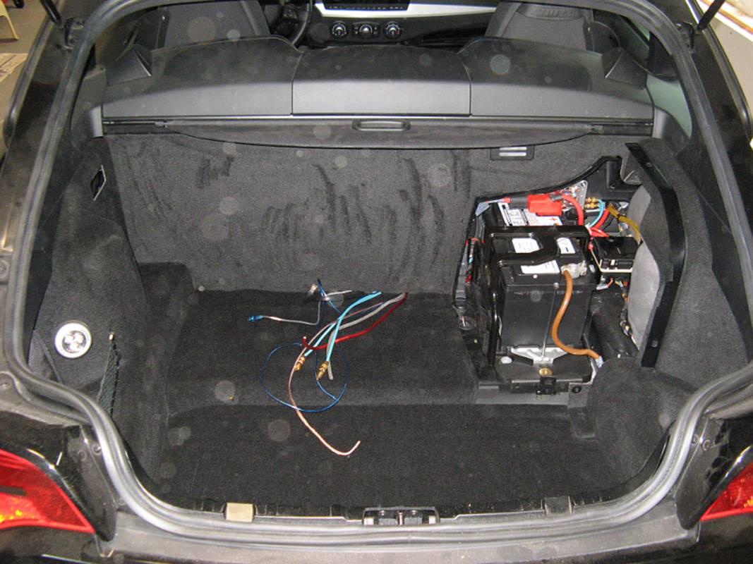
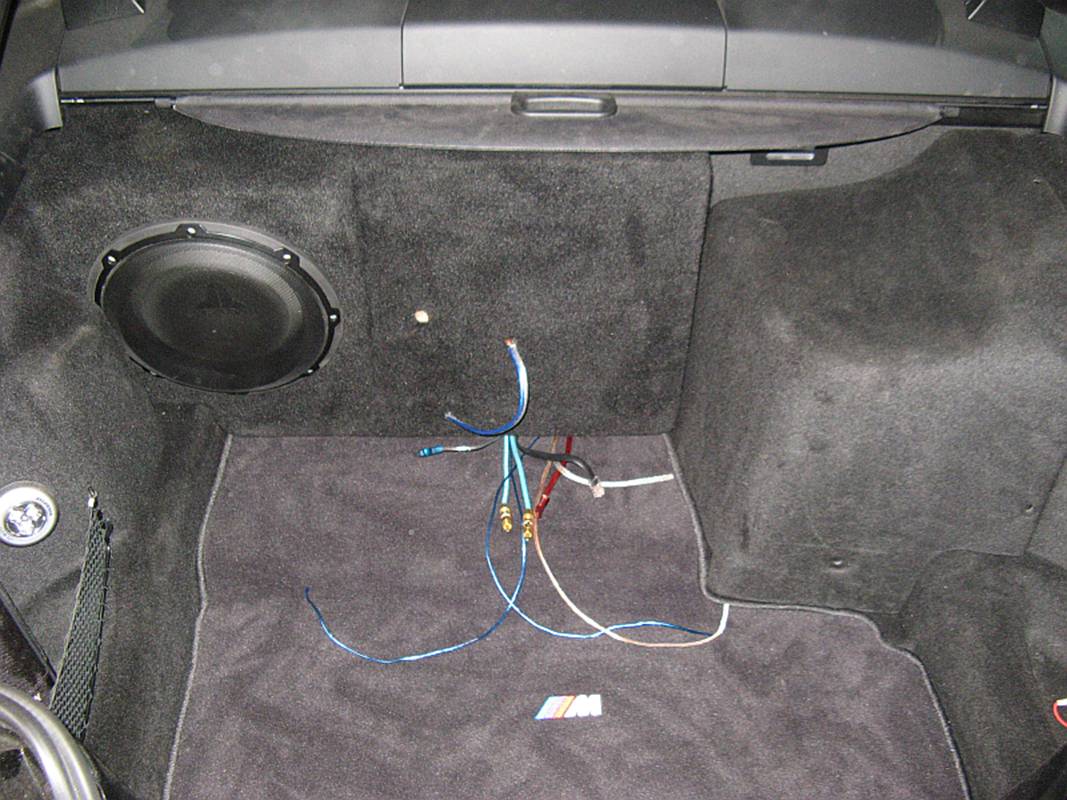
Here is
what we now have to work with, the iPod components can also be seen here (Intravee
II and Alpine adapter):
WIRING:
I started
my installation by further investigating the OE amplifier pin-out for the Top
HiFi (A18) amplifier used in my car, and found the following wire colors
related to the subwoofer outputs from the amplifier, these matched the colors
that GV from
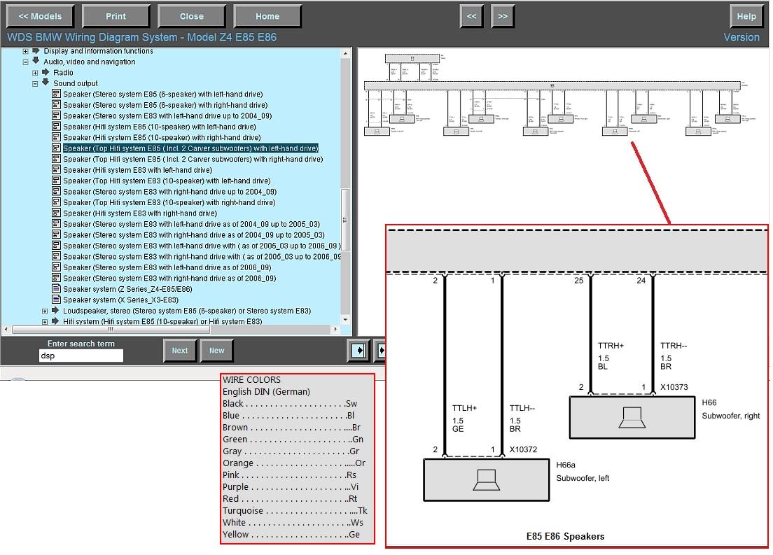
The wiring
schematics were researched on the BMW WDS (Wiring Diagram System) available
online at
http://www.bmw-planet.com/diagrams/release/en
. I also had to download an Internet Explorer SVG plug-in to use this website
which can be found at http://www.examotion.com/index.php?id=product_player_download
The
amplifier pin-outs with wire colors can be found at http://www.billswebspace.com/A18
Amplifier.htm -I have also included GV from
NOTE: Disconnecting the
battery ground wire before working with any wiring projects in the car is
usually a good practice. Also note that this might require resetting the pinch
protection for the power windows (roll down and press down button 4 times, then
roll up and hold a few seconds- auto up/down should work if successful) and
resetting memory for the radio and power seats.
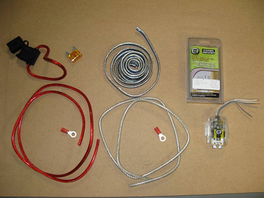
Before
beginning the project, I made sure I had some 8 gauge power and ground wire
with connectors for the amplifier, some 12 gauge speaker wire for the speaker,
a fuse holder and fuse, and some RCA patch cords. I also purchased a Scosche LOC80
line output converter to convert the high power speaker level outputs to line
level RCA inputs for the amplifier. After evaluating my goals and the results,
I ended up replacing the LOC80 with an MTX REQ (now marketed as a Streetwires
product). The factory head unit adjusts bass levels down once the volume
exceeds a certain point to save the factory speakers from damage, the REQ
compensates for this as well as providing line level conversion and noise
elimination circuitry:
To work
with the amplifier wiring harness, the amplifier is removed for easier access.
It is pressure fit and held in place with a Velcro strap. Once the Velcro is
undone the amplifier can be carefully pulled out:
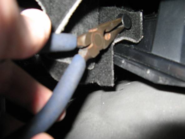
The left
side wiring harness can be removed from the plastic tie by pushing the retainer
ears together with pliers and separating:
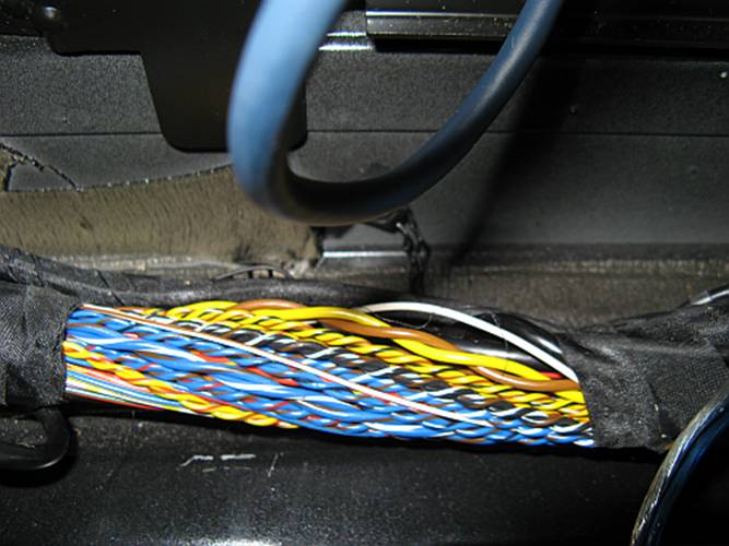
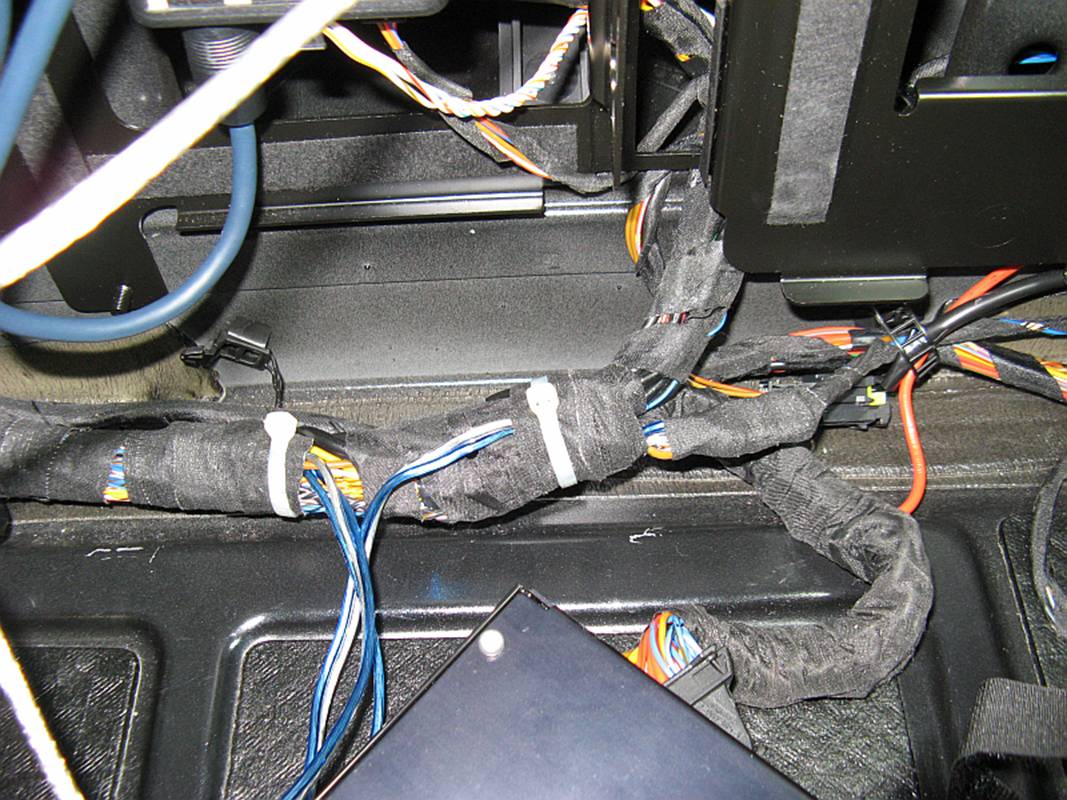
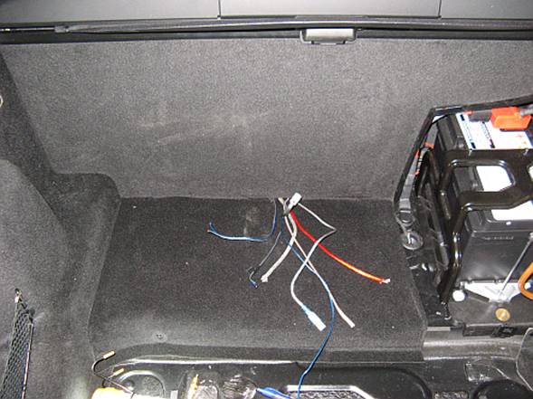
Here, the
fabric tape has been removed for wire access, the white wire at the top of the
picture is tapped for the remote turn-on connection and the yellow (+) and brown
(-) larger gauge wires are the left subwoofer speaker level outputs that will
be tapped for a line level converter:
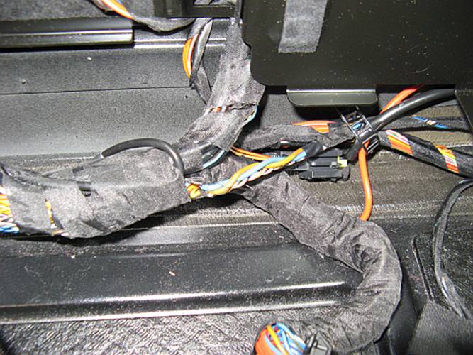
Here,
fabric tape again removed for access, the blue (+) and brown (-) larger gauge
wires are the right side subwoofer speaker level outputs found in the right
side harness leaving the amplifier that will need to be tapped for the line
level converter:
There are
various schools of thought on the best way to tap wires, but I used appropriate
gauge crimp connectors with the proper crimp compression tool as I have found
this to work better than solder and Scotch splice connectors in a mobile
environment, YMMV.
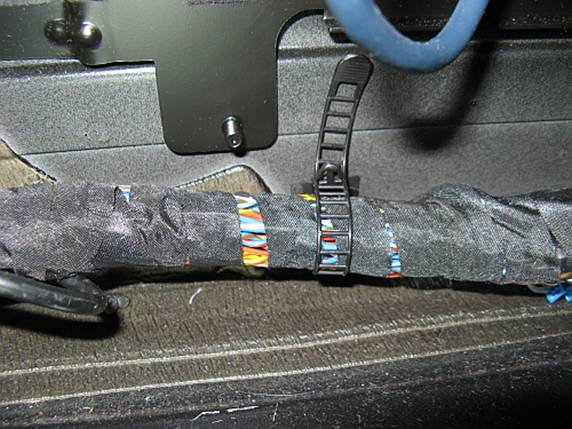
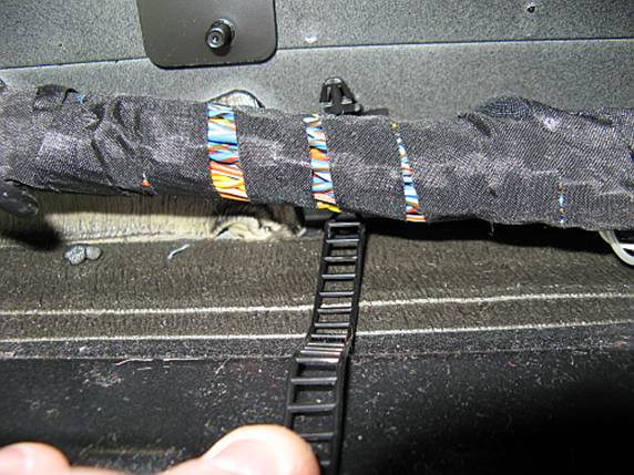
Once all
of the wires had been connected, I wrapped the wiring harness with new cloth
type electrical tape and used tie wraps to keep movement to a minimum:
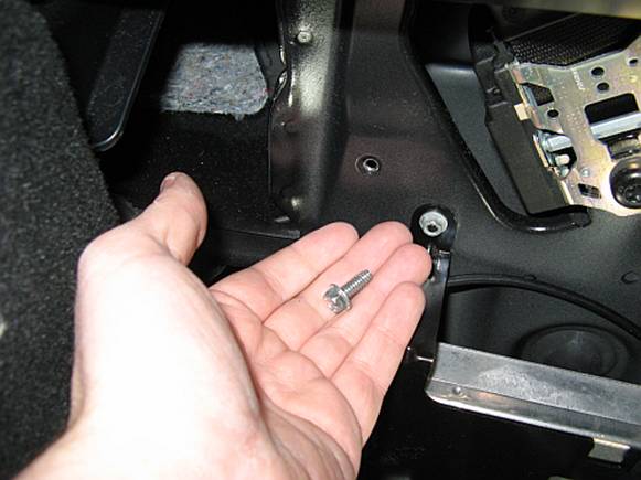
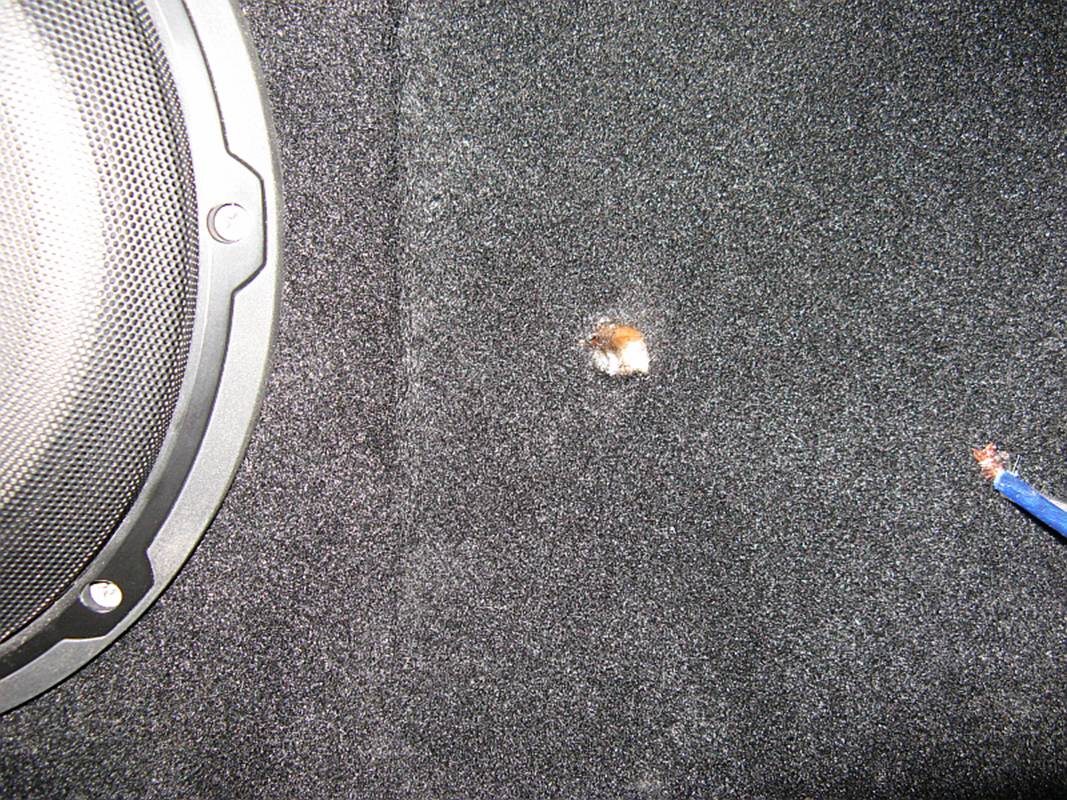
With the
subwoofer and remote turn on wires verified, the only wires left to hook up are
the ground and 12v+ wires. For the ground, I found an existing hole in the
bulkhead and after sanding away paint down to metal was able to find a sheet
metal screw that worked to secure the 8 gauge ground wire. Alternatively, there
are grounding junction blocks on either side of the car, one beside the battery
and the other in the same location on the other side of the car, identified by
the multiple brown wires terminating at each:
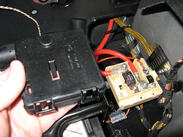
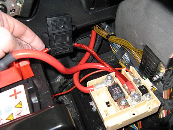
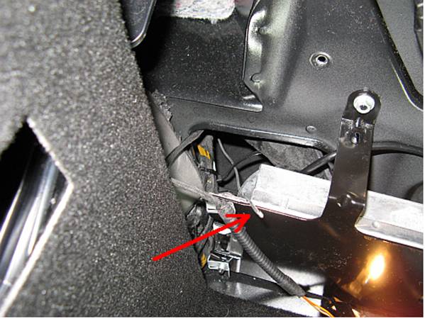
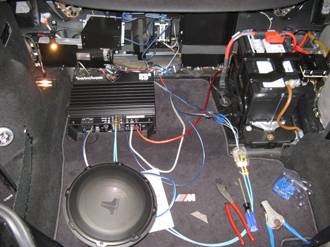
For the
12v+ connection I used the central battery connection on the distribution
block- cover is removed by unsnapping two snaps at the front and then tilting
back and off. Wiring between the 12v+ connection point and fuse should be kept
as short as possible. The reason I chose the center connection point in the
junction block was because it was BEFORE both the 230 amp main fuse and the 40
amp OE stereo amplifier fuse. I used a 40 amp fuse for the new amplifier fuse
holder, a large blade/maxi style fuse because it is easy to replace. The fuse
holder was installed WITHOUT the fuse, the amplifier
should be connected to all wires BEFORE installing the fuse:
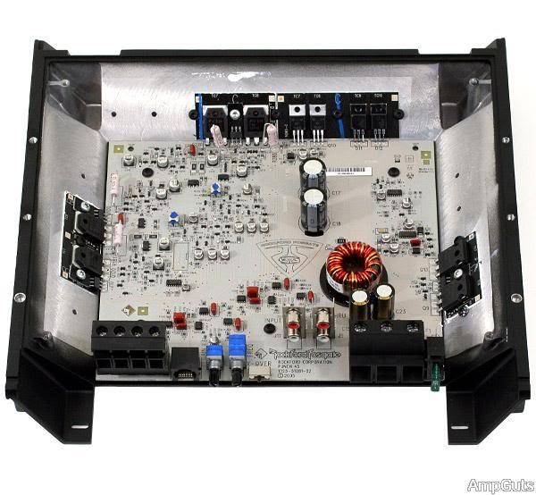
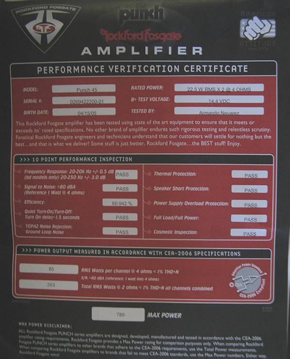
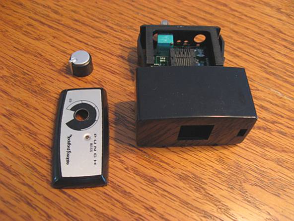
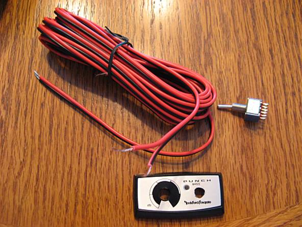
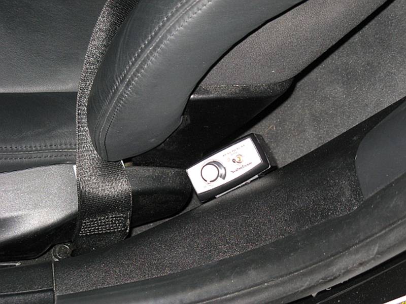
The
amplifier I decided to use for my installation is a Rockford Fosgate Punch 45
(25th anniversary model), partly for
sentimental reasons and partly for value- but in all honesty it is closer in
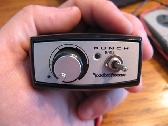
spec and size to the old Punch 150. This amplifier has a remote parametric bass
knob to control frequencies centered at 45Hz and boost them up to 18dB. Since I
also wanted to control whether the new additional subwoofer was on or not, I
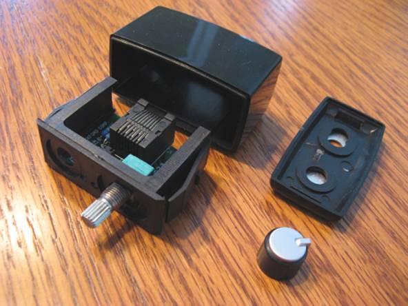
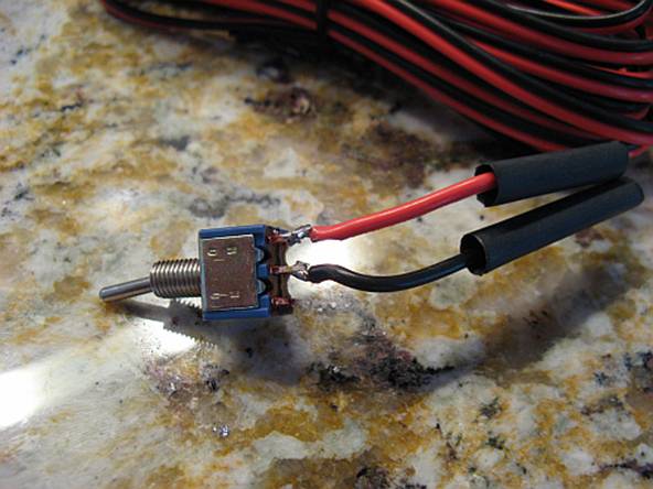
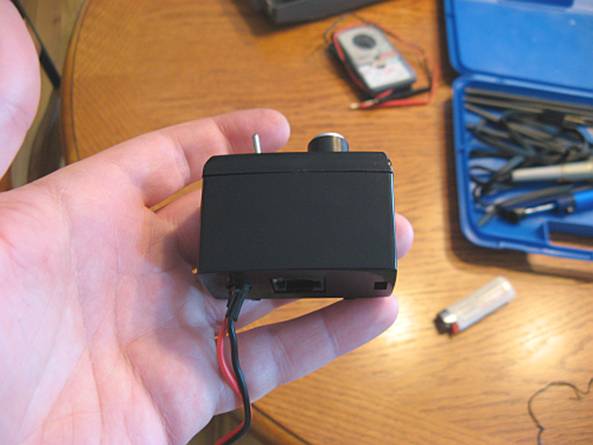
decided to modify the wired remote by adding a switch. The knob is removed by
pulling straight off and then the faceplate can be snapped off. The inside
electronics are help in place with two retainers, one can be released using a
screwdriver in the slot beside the connector and then the other will release.
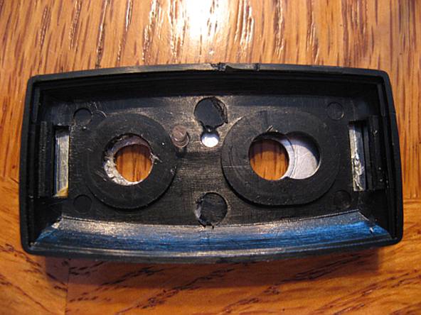
The switch has two wires that will splice in between the remote turn-on
connection and the amplifier. The faceplate already had one hole in the plastic
so a drill bit was used to drill a hole in the metal faceplate for the switch.
A hole was also drilled in the bottom for the new wires.
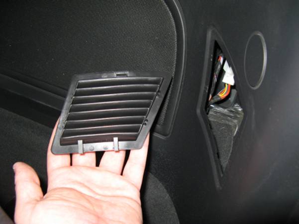
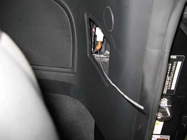
To run the
wires for the remote, the vent beside the sub can be removed using a
screwdriver at the top to snap out and then it can be pulled up and out. Some
rigid wire (coat hanger, baling wire) helps run the wire from the cabin to the
rear; wires can be attached with electrical tape and pulled through to the
other side:
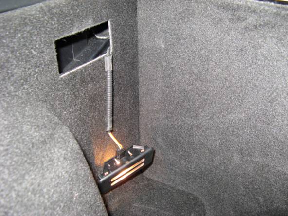
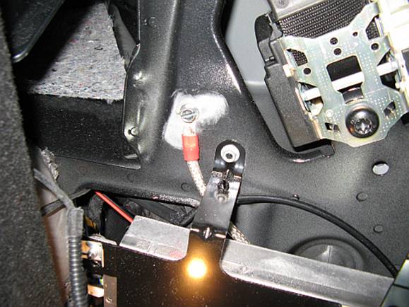
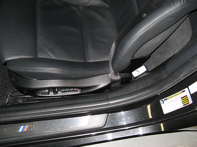
I chose an
accessible but out of the way mounting location, and its only two small holes
for the mounting plate. Wires were run under trim down to the mounting point:
Before
reassembling the bulkhead trim pieces, I thought it might be a good idea to
test the wiring by hooking the amplifier, LOC, and speaker up. Since everything
worked, it was time to move the speaker enclosure (box) from concept to
reality:
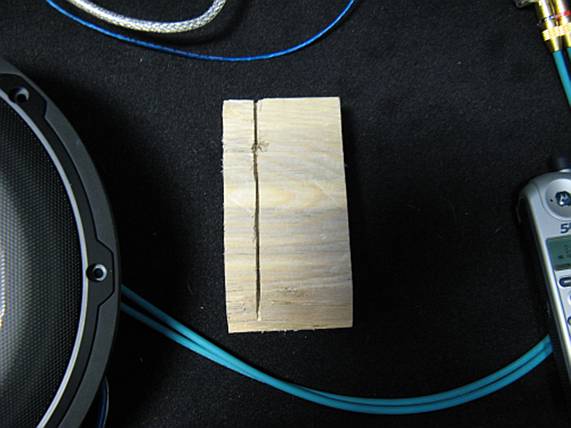
Also
before I reassembled the bulkhead trim, I made a wooden mounting point for a
lag bolt to anchor the sub enclosure. I chose a point towards the center of the
enclosure that happened to have a metal lip and a small bit of air space
between a mount and the metal wall. I filled the space between the empty mount
and wall using a small piece of thin wood and then used a saw to cut a small
relief on one side of a piece of 2”x4” wood to fit over the metal lip. The
2”x4” piece was then secured using two sheet metal screws (I was sure to feel
on the other side for wires or other critical things BEFORE drilling holes).
Additional pieces of wood were attached to this so that it was flush with the
bulkhead cover.
BUILDING THE SUBWOOFER
ENCLOSURE/SPEAKER BOX:
I
have built many different types of enclosures for many different cars in years
past as a sideline job and enthusiast, my goal with this car was to correct the
factory stereo low end without taking up all of my trunk space. I originally
wanted to use fiberglass but time and resources necessitated the use of good
old ¾” MDF. Because of the way the trunk is shaped and some of the weird angles
involved, I found cutting the pieces and fitting them in the car prior to
assembly was the best way to make sure I was utilizing all available space and
that the end result would be what I wanted. When fitting I took into account
that the carpet would require some additional space so pieces were cut about a
¼” less total per side than what would fit.
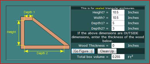
I
found the following websites helpful:
http://www.bcae1.com/spboxad2.htm
- Box calculator-find what sealed or ported box works best for your speaker
properties
http://www.bcae1.com/spboxnew2.htm
- Box calculator- find volume for given measurements
http://www.bcae1.com/carpetenclosure.htm - Carpeting a box
http://www.diysubwoofers.org/talkshop/messages/41415.htm
-Fiberfill use
http://www.diyaudioandvideo.com/FAQ/Build/
- Building a speaker box
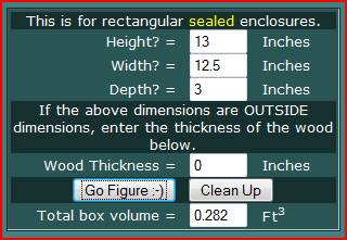
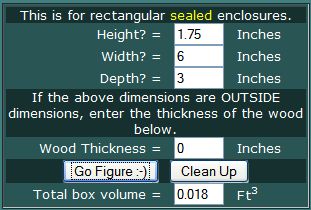
The JL 10”
speaker used required .625 Ft3 of air space according to the JL
Audio manual. I had this same speaker in a JLA StealthBox in my Lotus and that
box only had .45 Ft3 and was filled with poly fiberfill…..and it
sounded great. The box I designed was going to have .52 Ft3 of air
space (total volume of .555 Ft3 - .025 Ft3 speaker volume
- .01 Ft3 brace volume) and with poly fiberfill should effectively
be .676 Ft3 figuring 30% perceived volume increase. Since most boxes
act smaller than their calculated volume would suggest, this should be right
around the JLA specific volume of .625 Ft3
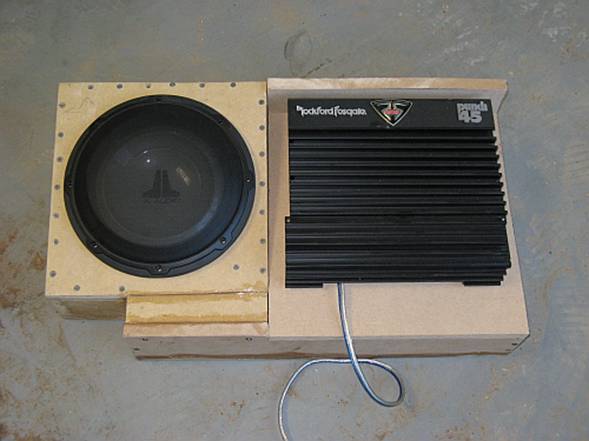
Speaker
side of box:
Amplifier mounting side of box: Small section under speaker:
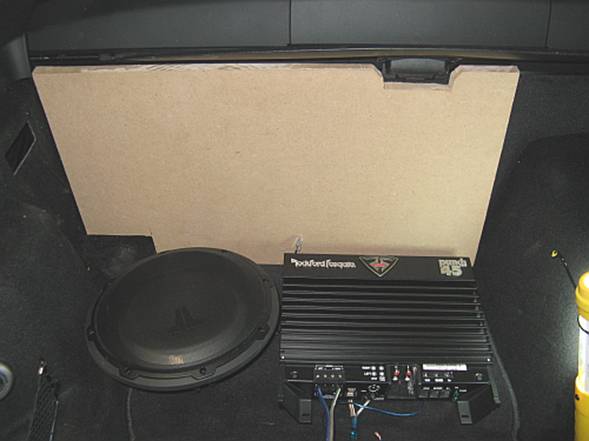
Bulkhead
cover reinstalled (wires run through small slit cut with razor knife) and
measuring/fitment of enclosure panels takes place. I debated whether to flush
mount the amp or not but decided that since the entire housing acts as a heat
sink I would just mount it on the box with some visibility of the wires going
to it:
Clear
silicone was used (but wood glue works too) between each panel and then panels
screwed together with fine thread drywall screws, a larger drill bit was used
after pre-drilling small holes for screws so that the head would sit flush with
the surface- be careful NOT to apply a lot of pressure or you will be drilling
a hole rather than providing a slight relief for the screw head. With MDF if
you do not pre-drill holes you WILL split the wood. Also remember that the
sander and carpet will make it all look nice when finished.
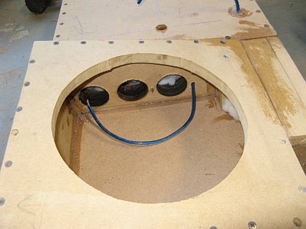
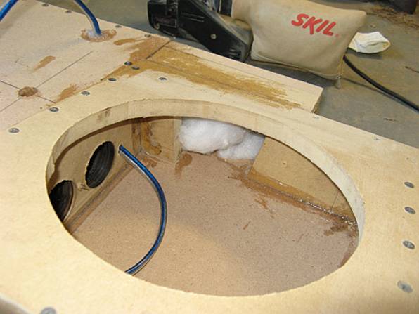
After the
box was assembled, poly fiberfill was used to pack the enclosure to effectively
make the box seem larger. Since this box was small I used the rule of 1.5 lbs
of fiberfill per 1 Ft3 for a total of .75 lb of fiberfill. Here you
can also see some of the braces. Since the speaker panel was effectively braced
on all four sides closely, I did not double the thickness of the wood on the
face for mounting the speaker-if the speaker facing is larger, this is
something that should be done. Speaker wire was run through one of the braces
so that it would not rattle in the box and out the amplifier mounting face
board- sealed with silicone inside and out. Fiberfill was used in the speaker
location as well, although not pictured below (remember to leave enough room for
the magnet structure).

No
pictures taken at this point, but when the box was completed it was tested in
the car with the speaker installed for sound and air leaks. It sounded fine and
no leaks existed so back out it came for carpeting. Prior to carpeting a sander
was used to smooth any imperfect surfaces and to round the corners and edges of
the box. Carpeting the enclosure was done with 3M Spray 77 spray adhesive
(applied to both box and carpet surfaces and allowed to tack before applying
carpet), I found it easiest to do the box face first and then one side at a
time. The carpet I used was acoustically transparent carpet with no backing,
the lack of backing makes it easy to shape and stretch around angles and
corners with limited or no cutting…..and the carpet was a perfect match for the
BMW trunk carpet. Before the speaker was installed fiberfill was used in the
speaker area, leaving enough room for the magnet and motor assembly to fit and
breathe.
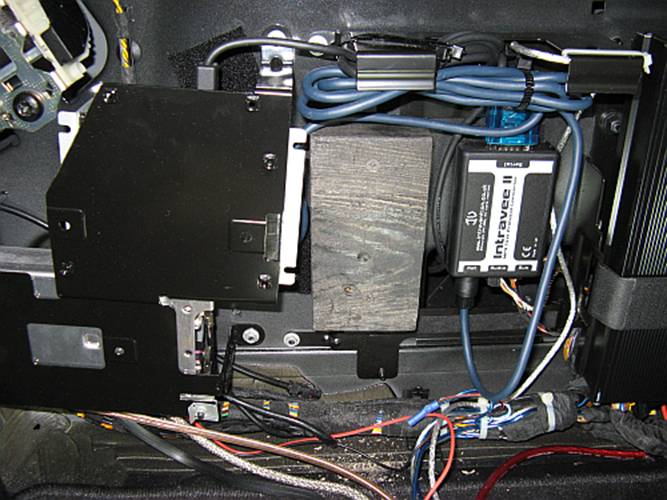
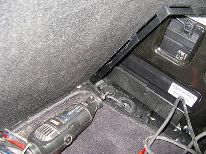
Since the
box fit very flush against the battery
cover, the lower slot had to be elongated to allow the lowest hook to enter
nearer the top, using a Dremel tool this was done to within a half inch of the
top most slot. I did this with the cover pulled out to avoid contact with the
battery cable.
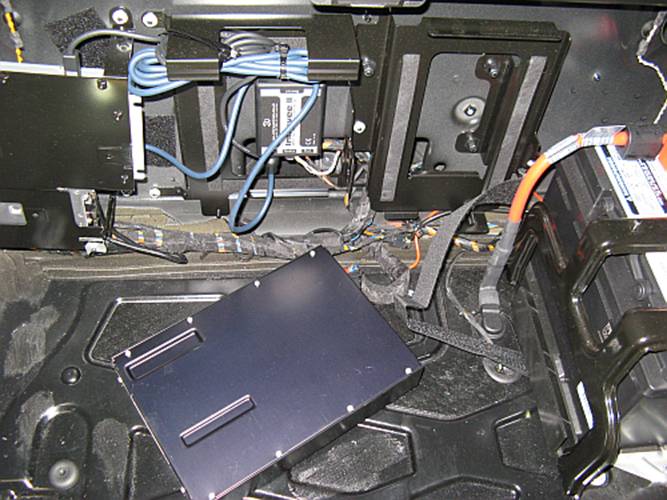
I also had
to move the luggage compartment light since the box covered it; I chose a spot
above the battery cover on the bulkhead cover and again used a Dremel tool to
cut the hole. The bulkhead cover is about $130 from the online discount BMW
parts dealers so I will probably order one just in case I ever decide to return
the car to stock. I figured I have to cut slits for the wires anyway……. You can
also see the REQ mounted in front of the battery to the bulkhead, I used
industrial adhesive Velcro but positioned it so adjustment could be made with
it in place-all signal wires cross battery wires at perpendicular angles and
there is NO noise with car running and alternator charging at high current (I
know this because I had just enough charge to crank the car after it sat with
the door and hatch open all day after sitting without being driven for two
weeks and then initially testing the system a few times….). The bubbles in the
pic below are sawdust floating in the air…clean up after installation was the
worst part:
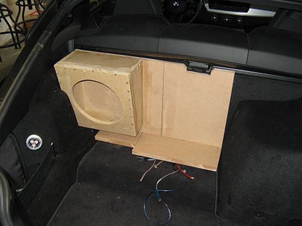
Enclosure
installed, note the hole in the center of the box. This hole goes through a
brace sealed from the inside. The hole is just large enough for a lag bolt and
washer to go in with a socket and extension. Tightened just hand tight so the MDF
does not get damaged, the top edge of the box rests against the bulkhead metal
rail so the one lag bolt should be plenty to keep movement restricted, the box
looks like it was poured into place anyway:
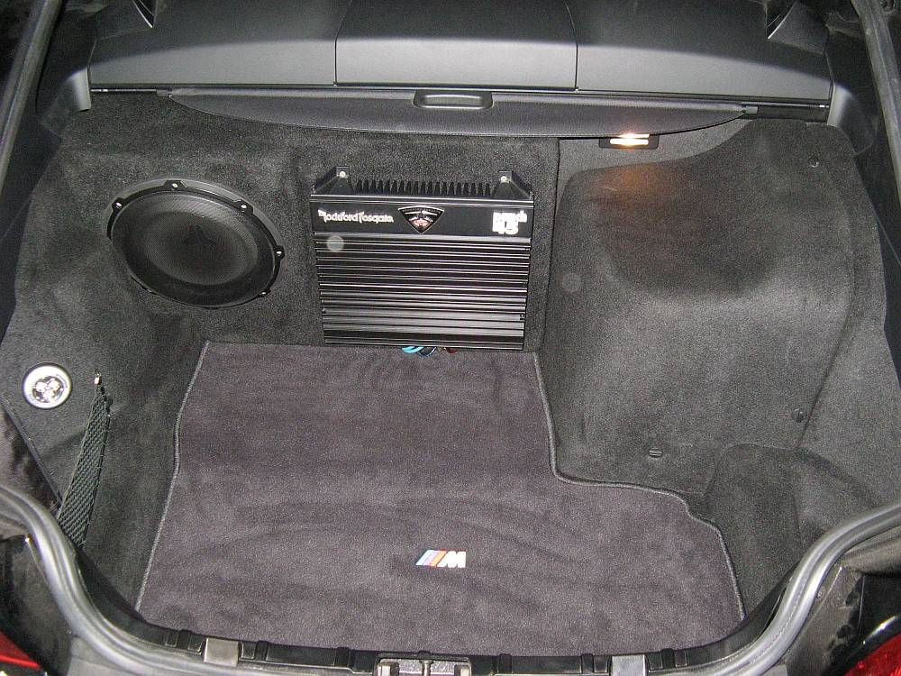
Amplifier
wires connected and cover plate attached, the hatch cover fits right on top of
the box when snapped down on to the base, box was recessed for clearance of the
hatch cover handle and base:
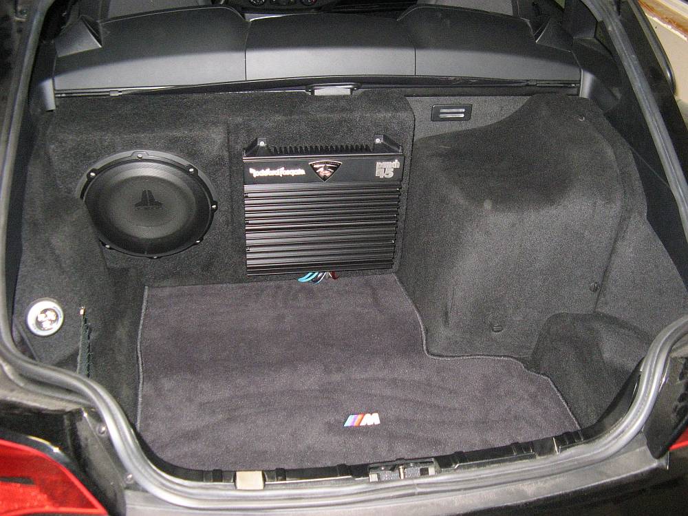

Overall I
am pleased with the aesthetics and sound, this low end addition corrects a lot
of what I was unhappy with. I don’t think it sounds as good as a complete new
system but for an add-on sub integrated with the OE head unit and amplifier, it
sounds GREAT. For a single 10” subwoofer, this speaker moves enough air to
sound good with rap but is also accurate enough for jazz, rock, classical, etc.
I listen to a lot of different genres of music and so far I am quite pleased
with my $400 investment and a little time. At some point I may go back and do
it again in fiberglass.