![]()
![]()
![]()
Mazda Miata NC : My
Flyin Miata Springs/Shocks Installation
When I was searching for write-ups to see what was involved
with this there were only a few and not many with pictures. The best was Brian
Goodwin's write-up: http://www.mazdatalkforum.com/viewtopic.php?f=9&t=659
Since his addressed coilover installation and I was
installing springs/shocks, I decided to compile some pics and information for others.
![]() Standard Disclaimer: The following is my experience provided
for informational purposes only, any use of this information by other parties
to conduct installation is at their own risk, no warranty/guarantee
that information is accurate is expressed or implied.
Standard Disclaimer: The following is my experience provided
for informational purposes only, any use of this information by other parties
to conduct installation is at their own risk, no warranty/guarantee
that information is accurate is expressed or implied.
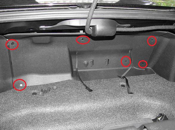
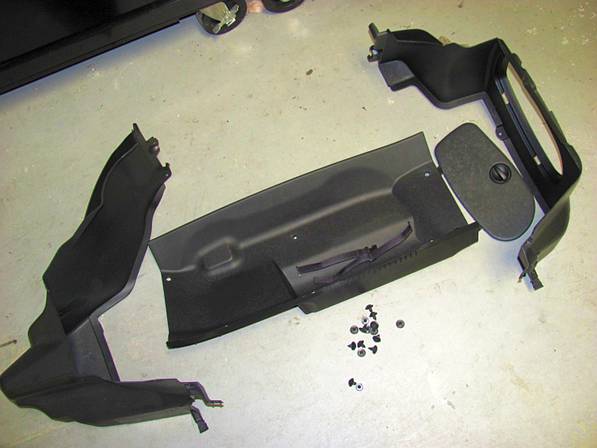
Removing Trunk
Panels
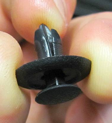
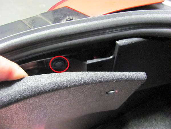
Because the last thing I want to do after getting dirty is
remove the plastic panels in the trunk, I did this first. All are held in place
with plastic rivets, by using a small screwdriver or pick the center section
can be pulled out to release them and they can be removed from the panels. I
started with the front panel then moved on to the side panels. I did not remove
the rear panel but was able to flex the corners enough to remove the single
rivet on either side.
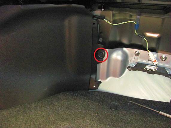
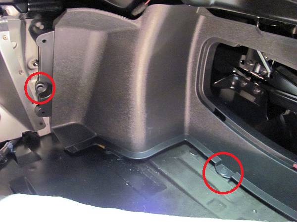
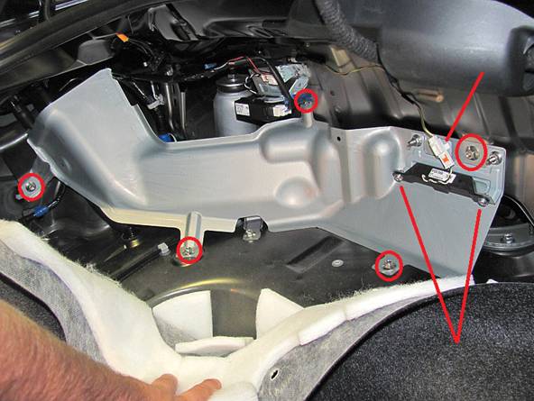
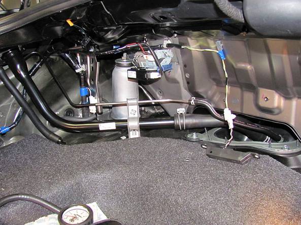
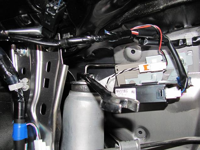
Now that all of the plastic pieces are out, you will notice
a metal shield on the driver (left) side of the car over the gas tank hose. If I had known then what I know now (you'll
see as you read further), I would have left this in place. But because I
thought I was removing the entire rear assembly I did remove this, just a few
bolts and a small module need to be removed (release plug/socket using needle
nose pliers)- Phillips screwdriver to remove module and 10mm socket wrench for
bolts.
Front Springs and
Shocks
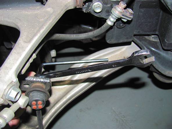
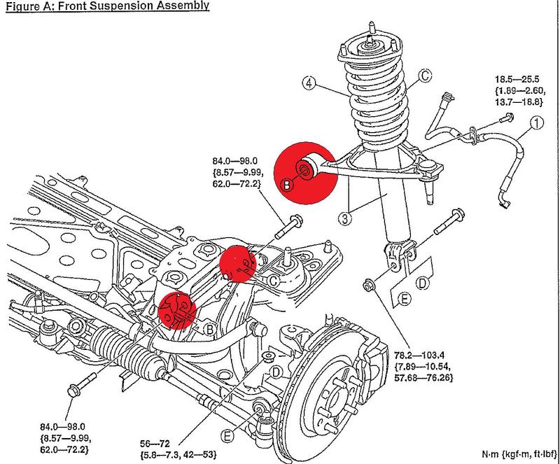
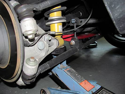
After getting the front of the car on jack stands (both
sides), the sway bar end-link can be removed using a 6mm HEX to keep the stud
from spinning and a 14mm wrench to remove the bolt.
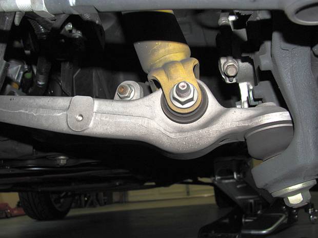
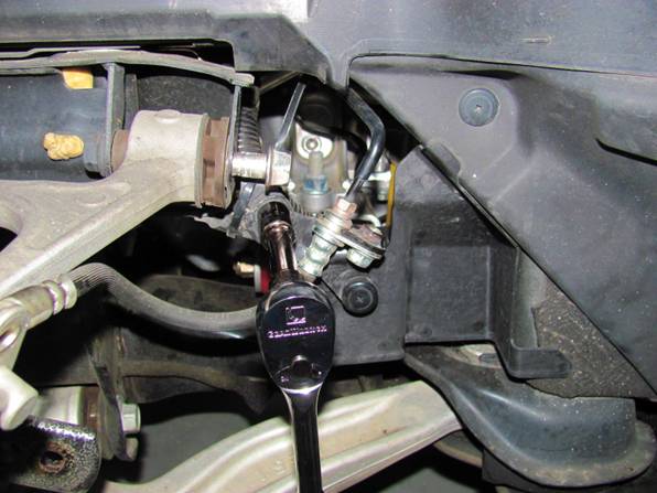
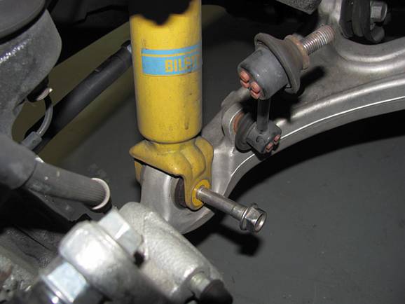
Use 17mm wrench(s) to remove lower shock mounting bolt/nut.
If you can remove the nut but not pull the bolt out all the way, no worries- it
will come out easier after a few more steps.
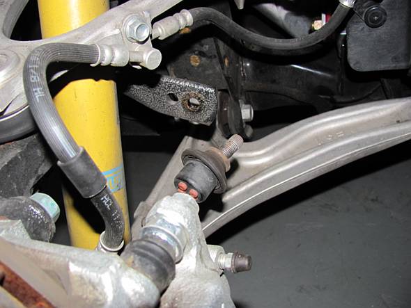
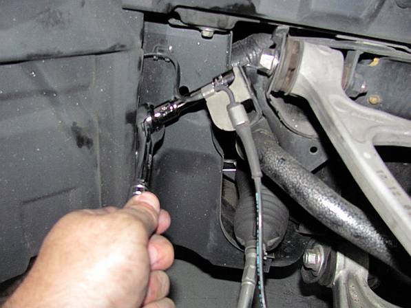
Next the
ancillary items that need to be freed are the brake lines and brake sensor
wiring. Using a 12mm socket and extension, the brackets can be removed from the
chassis and a-arm so that there is room for them to move without damage and so
the upper a-arm bolts can be removed. You will also need to use a Phillips
screwdriver to remove the plastic rivet holding the brake fluid hose bracket to
the plastic shield.
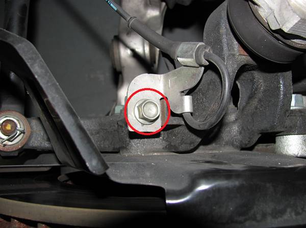
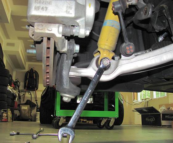
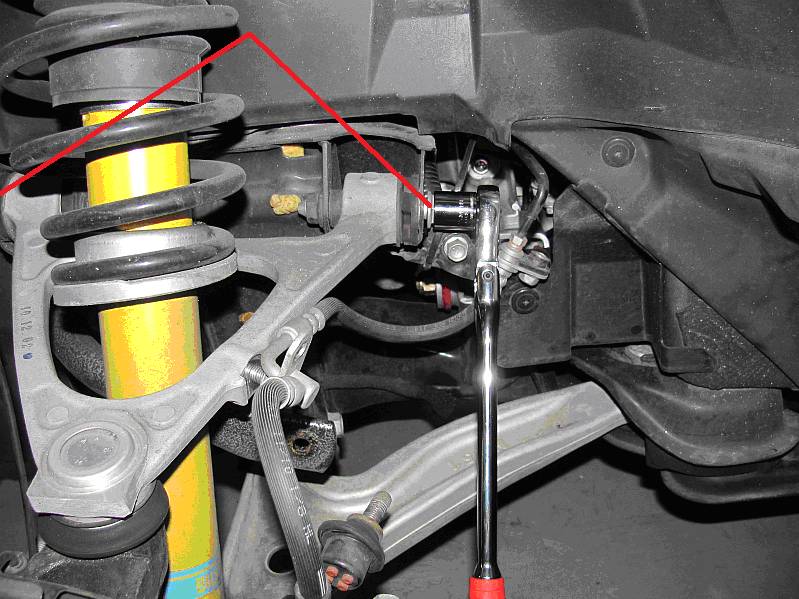
The upper
A-arm bolts (two per side) are then removed using a 17mm socket and breaker bar
or ratchet.
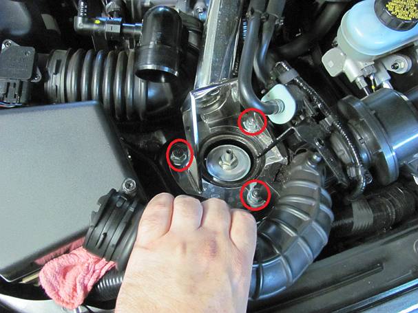
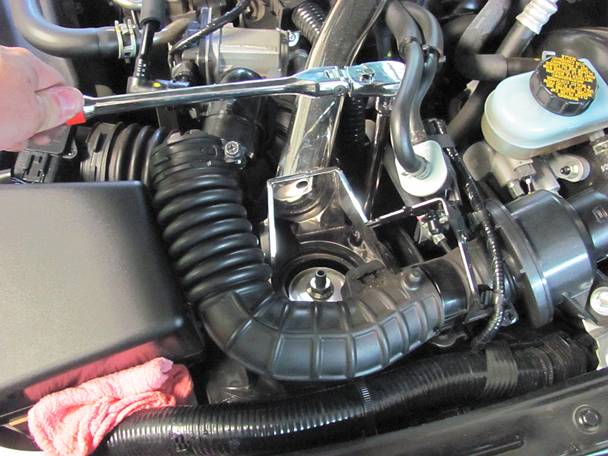
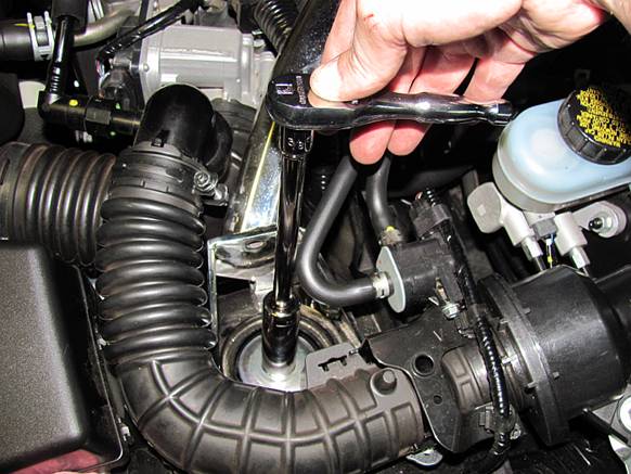
Up top,
the three shock tower nuts need to be removed. On the driver side the intake noise
tube has to be removed in whole or in part using a 10mm socket for the hose
clamp. I just loosen one clamp and flex the tube out of the way for access.
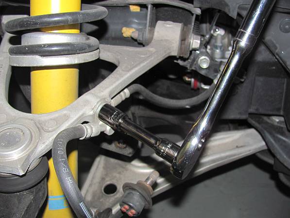
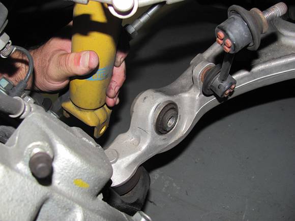
With the
upper three nuts removed, the bolt can be removed from the lower shock mount if
you were unable to earlier and the shock can be pulled to the side and off the
lower a-arm.
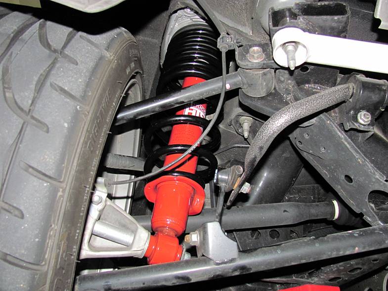
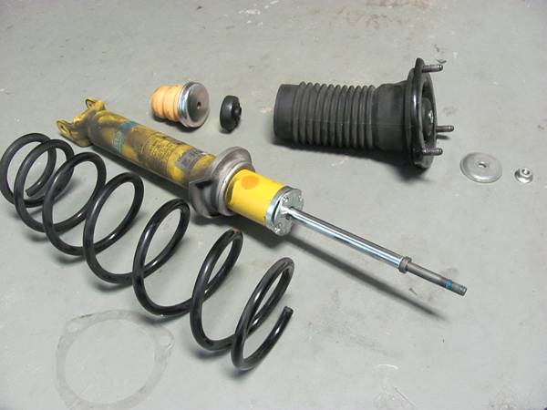
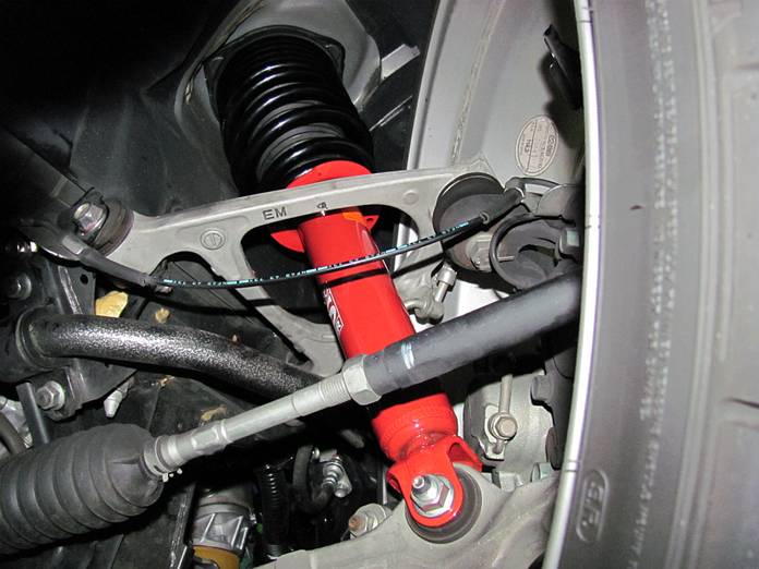
The
shock/spring assembly can be pulled down in front of the lower a-arm and then
maneuvered out under the fender (and yes there is the jack you can see but also
jack stands you cannot see- don't trust a jack).
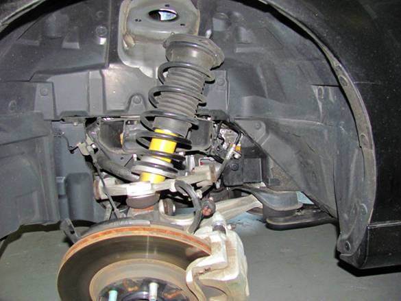
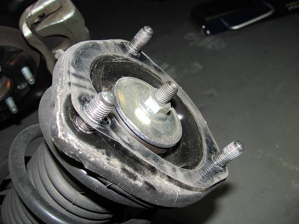
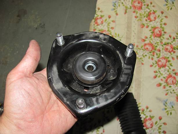
I removed
the thin plastic sheet at the top of the shock assembly- don't forget to
replace it before installing the new setup as it prevents noise. Also note the
orange sticker on the shock, this is the side that faces toward the inside so
you will need to orient the new shock the same way- I used the lower spring
stop as a reference point, the stop is always towards the inside.
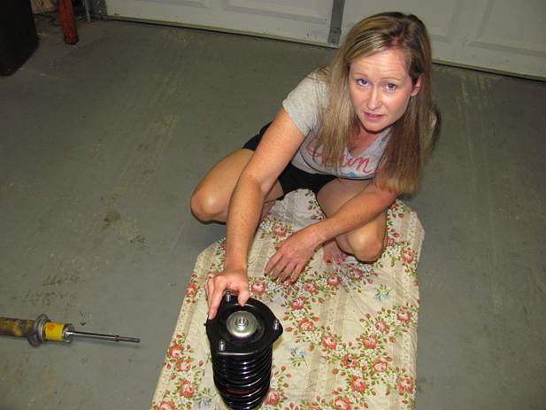
SO
everything is left hanging up front while the old shock/spring are disassembled and the new parts assembled. Note the brake
wires and line, this is why the brackets are removed
to create some slack.
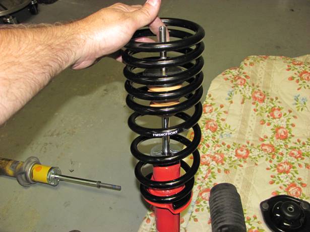
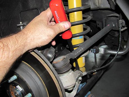
A spring
compressor should be used for safety (NOT pictured),
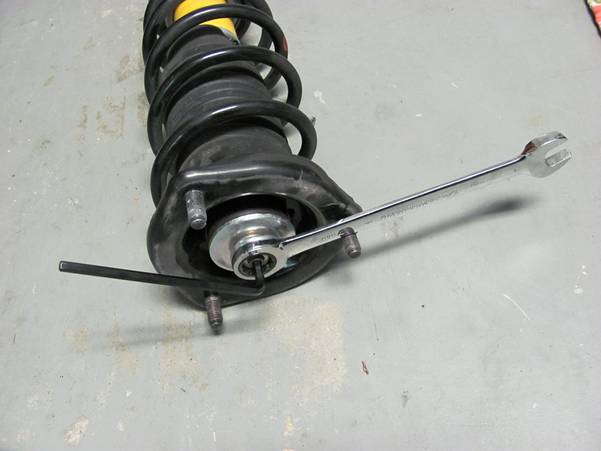
the front spring is still under a good bit of tension. The top shock nut can be
removed using a 6mm HEX and a 17mm wrench.
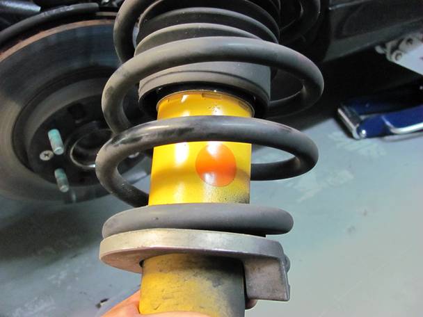
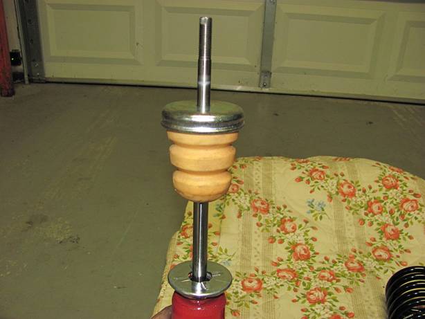
The FM
springs are marked front and rear, make sure the
correct one is used for assembly. I started by placing the bumper and washer on
the shock, then the spring making sure the end sat in the stop, and then the
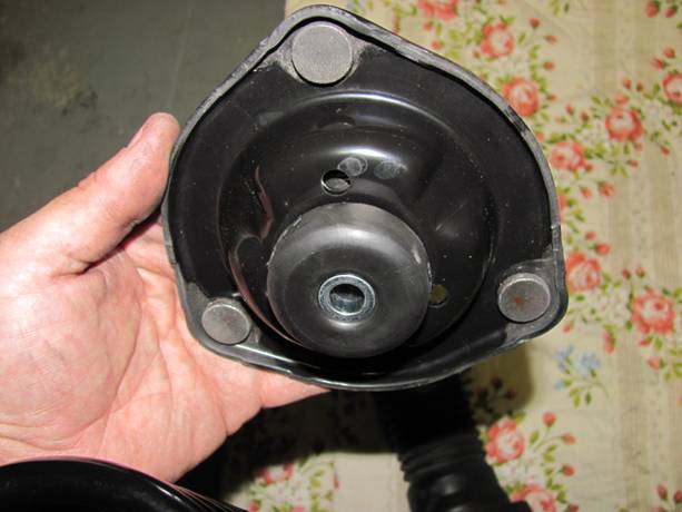
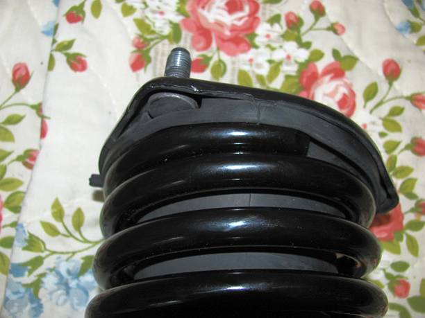
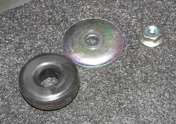
top mount consisting of two rubber donuts and a central steel spacer with
bellows. Note that the rubber bellows has recesses for the three studs on the
upper mount and is positioned accordingly. While I compressed the assembly my
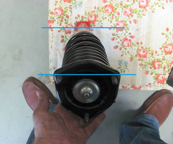
wife was nice enough to add the washer and thread the nut on. While doing this
step you need to visualize where the top mount needs to be in relation to the
bottom mount and position it as you compress it, this will make life a LOT
easier during installation. I lined up the lower bolt and the top two studs
making sure the spring stop side was on the same side as the two inside studs
on the upper mount. The top shock nut was installed as tight as possible by
helper/hand and then final torque was done after all other assembly was
completed with a short ratchet by hand to avoid the too tight/I sheared my HTS
rod off scenario. As you can see, I re-used the factory nut instead of the new
nuts supplied with the HTS shocks that rely on a double-nut approach to lock
them in place.
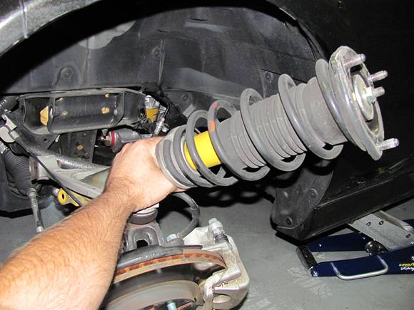
Reassembly
is the reverse of removal. You can use LocTite on the removed bolts, it should be easy enough to see what color was used
from the factory (red or blue). The upper A-Arm bolts and the lower shock mount
bolt/nut should be torqued to final spec only after the car is back on the
ground and rolled back and forth a few times to obtain the static ride height-
this will prevent bushing bind and failure. I started these bolts until they
were just loose enough to move, lowered the car, rolled back and forth by hand
a few times and then drove on to ramps to torque the bolts mentioned using a
17mm socket and torque wrench.
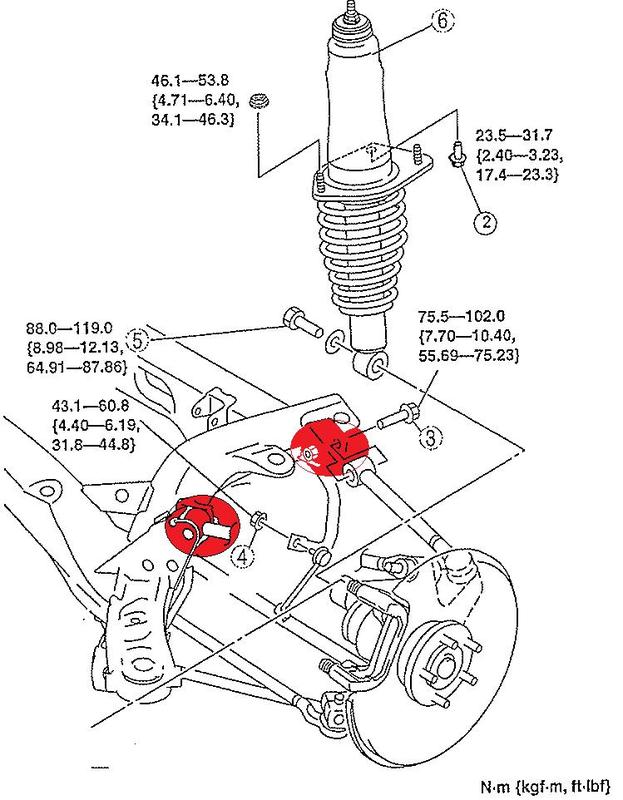
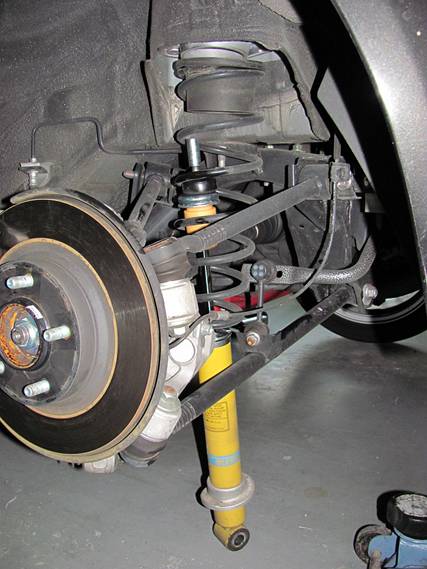
Rear Springs and Shocks
As
mentioned earlier, I removed the metal shield in the trunk thinking I would be
removing the entire assembly as I had in the front. But I happened to stumble on
a few forum posts that suggested an easier way that did not require a spring
compressor. I
WOULD NOT RECOMMEND THE FOLLOWING PROCESS AS THERE ARE SEVERAL WAYS TO DO THIS
INCORRECTLY THAT MIGHT RESULT IN PERSONAL INJURY- I ASSUME NO LIABILITY.
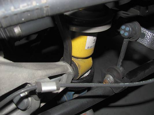
Using a 6mm
HEX and a 17mm wrench (I initially used a LONG wrench to break the upper shock
nut loose), the upper shock nut is removed along with the rubber donut and
washer.
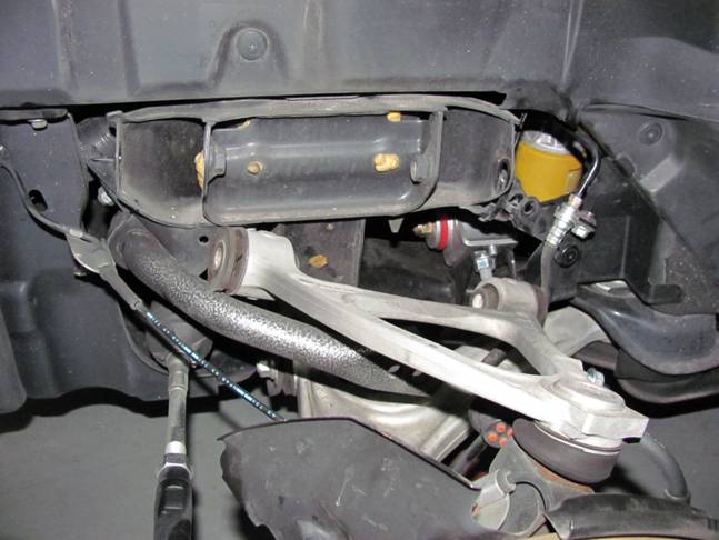
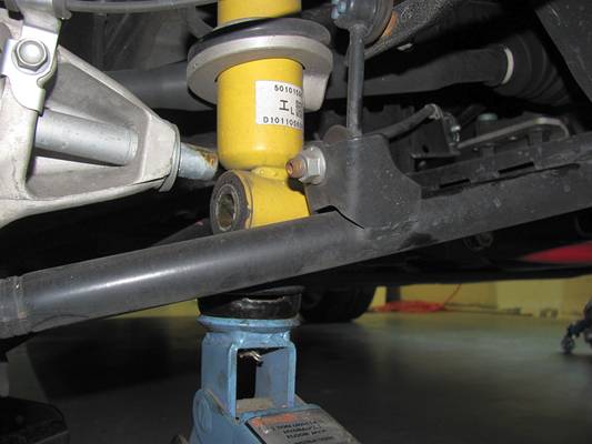
Then, a
jack was used to support the base of the shock and the lower shock bolt was removed
using a 17mm socket wrench. The shock will not drop since it is not supported
by the bolt, the lower shock bushing is supported by a
spindle on the lower control arm. While the jack is supporting the shock, a pry
bar can be carefully used to slide the shock off the spindle. The jack will
move with the shock and should result in no drama but care must be used since
the spring is still under tension.
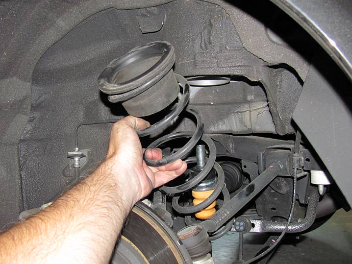
Once the
shock was off the spindle I lowered the jack to relieve spring tension and
pulled the spring out from the top, the shock out from the bottom- spring has
to be removed first so the shock will come out. It took a few minutes to get
the new shock and spring with the bumpers situated correctly so they could be
reinstalled but it only took an hour for both rear sides- QUICK. Again, note
the orange sticker as the side installed to the inside, also on the lower
spring stop side.
Reassembly
is the reverse of removal. You can use LocTite on the removed bolts, it should be easy enough to see what color was used
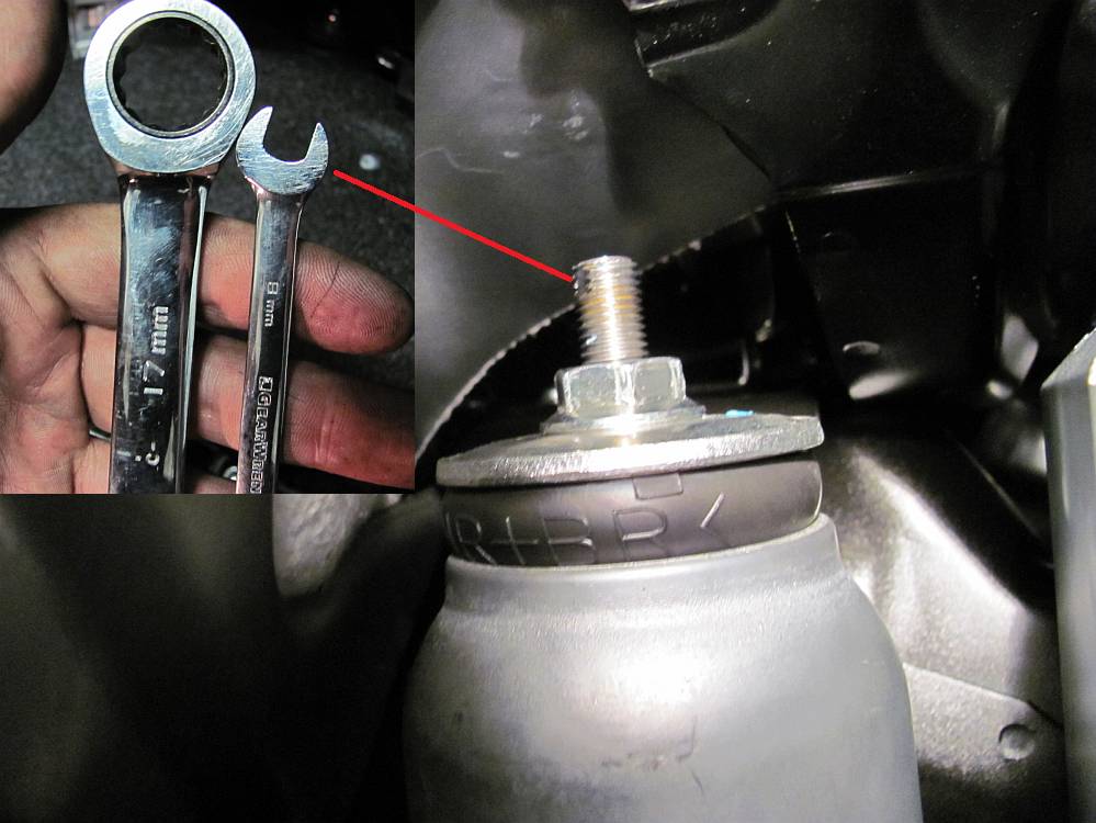
from the factory (red or blue). The HTS shocks have a spot at the top of the
threaded shock shaft for an 8mm wrench to hold the shock shaft while the nut is
tightened using a 17mm wrench, I re-used the factory nut instead of the new
nuts supplied with the HTS shocks. The upper connecting rod bolts and the lower
shock mount bolt/nut should be torqued to final spec only after the car is back
on the ground and rolled back and forth a few times to obtain the static ride
height- this will prevent bushing bind and failure. I just loosened these bolts
slightly so that the bushings could move (no more), lowered the car, rolled
back and forth by hand a few times, and then drove on to ramps to torque the
bolts mentioned using a 17mm socket and torque wrench.