![]()
![]()
![]()
Installation
Instructions for
http://www.elisetalk.com/forums/showthread.php?t=38005
- Remove the engine under-tray using a method with which you are comfortable. The method I used was to place a large piece of cardboard on the floor under the tray and remove all the small bolts from the sides and rear of the tray. Then the two larger hex (Allen) button head screws were removed and the tray pulled slightly rearward and dropped onto the cardboard. Slide the cardboard out from under the car with the tray on top of it and clean and place the tray somewhere where it won’t get stepped on or damaged.
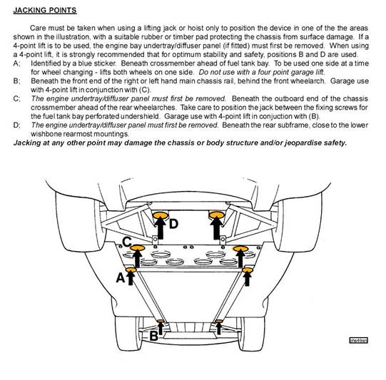
- Lift the car using the official lifting points B and C as shown in the illustration below from the owner’s manual. If using a floor jack, jack up each side of the car using jacking points A and place jack stands under the lift points B and either C or D (using D will require removing the rear diffuser).
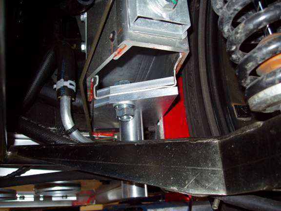
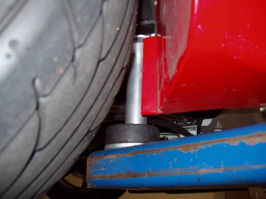
- Carefully examine the extruded aluminum frame openings on both sides of the car just forward of the lower rear A-arms for any burrs or sharp edges using a gloved hand. This is the place the frame plates from the kit will be installed. The end of the frame is crudely cut off to clear the forward edge of the A-arm and there can be many sharp edges. Also check the hole in the frame (where the mounting bolt for the frame plates will go) for burrs on the inside and remove any sharp edges or burrs with a file that will cut you or interfere with the sandwich plates fitting flat against the frame surfaces.
- Insert the upper frame plates into the frame openings making sure to use the plate with the cut out on the left hand (driver’s) side and with the angle end following the cut of the frame.
- Drop in one of the 1 ½” flange head bolts through the upper frame plate and frame hole so the threads are visible from under the frame.
- Assemble the flat head hex cap (Allen) screws using a 5/16” Allen wrench on the screw and a ¾” wrench on the nut into the countersunk holes in the lower plates using the thin lock nuts to tighten them into place.
- If you intend to leave the lift kit extension pins in place, it will be easier to install them with the lower frame plate off the car so screw the pins onto the lower plates now and tighten them in place with a strap wrench using a bench vise to hold the plates (or other tools suitable for the job). A drop of Loctite thread locker on the screw threads before assembly might be a good idea as well.
- Check the area of the frame where the rocker panel lip is glued to it by holding the lower plate in place to see if it fits flush to the edges of the frame and rocker panel. Trim off any excess adhesive as necessary with a razor blade or knife that causes misalignment of the plate with the frame.
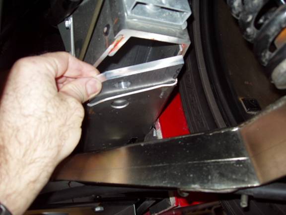
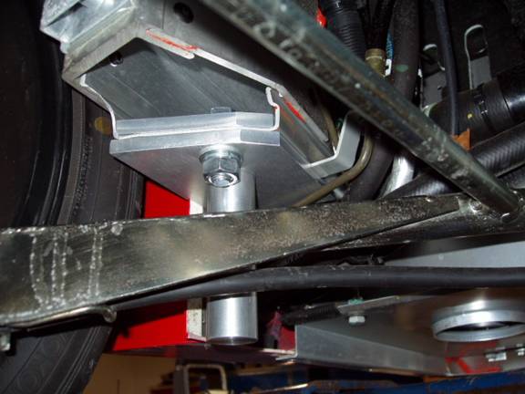
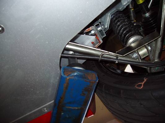
- Assemble the lower plate to the underside of the frame by holding the plate up to frame so the loose bolt passes through the hole in the lower plate and the notch in the plate fits around the inner rocker panel lip. The lower plate for the left (driver’s) side has a relief machined into the face to clear the clutch hose bracket so slip it between the clutch hose tube and the bracket. You may have to tweak the tube slightly if it is tight to the lower plate. Be gentle and only move it enough to give clearance between it and the lower plate.
- Thread the flanged locknut onto the bolt and use two ¾” wrenches or one wrench and a ¾” socket/extension/ratchet wrench combination to tighten everything into place. An air ratchet or impact wrench would make this even easier. While tightening the bolt, make sure to keep the plates aligned with the frame cut off and the rocker panel lip.
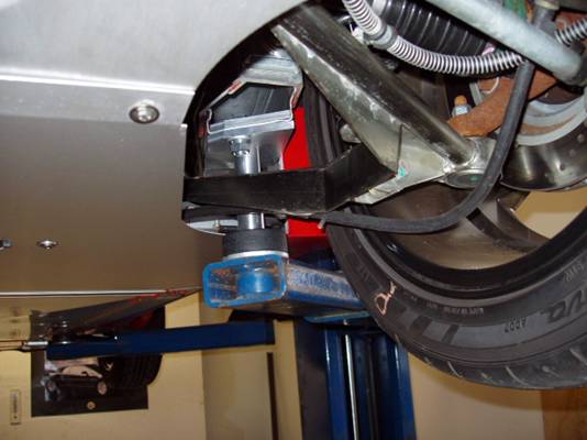
- If you installed the plates without the extension pins, thread them on by hand now.
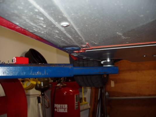
- Lower the car to the floor and carefully position your lift arms under the forward B lift points and the new lift pins. Start lifting the car slowly and inspect the lift points at the frame for any misalignment, bending or flexing. If anything does not look right, lower the car immediately and correct the problem.
- Once you are sure everything is correct, lift the car to a normal overhead height and do a thorough walk around under the car to establish that the lift points are secure. This may also be a good time to do a check of the engine compartment as well as a good time to check the torque of the rear links.
- Once you are satisfied with the inspection, pick up your under tray and slip it into position under the engine compartment. I find it easiest to slip the cutouts for the rear wheels over my lift pads and slip the rear lip of the under-tray under the forward edge of the rear diffuser, then push the under-tray rearward until it contacts the extension pins. Now slide the tray up and forward so its lip slips into the channel in the chassis and then press the tray up to the two center mounts and loosely install the two hex headed (Allen) screws. Install all the small bolts around the edges and tighten them in place and lastly tighten up to two center screws.
- Lower the car and if you are intending to remove the extension pins remove them at this time and put them in a secure place.
- From now on it is simply a matter of placing the lift arms under the pins and forward lift points and raising the car. If you are intending to use the lift points with a floor jack or jack stands, be sure to not lift the car at large angles to the extension pins. Having the pins tilting on your jack saddle will impart a twisting force to the extruded frame that may cause frame distortion. Carefully monitor the frame extensions when using a jack and stop before you damage anything.
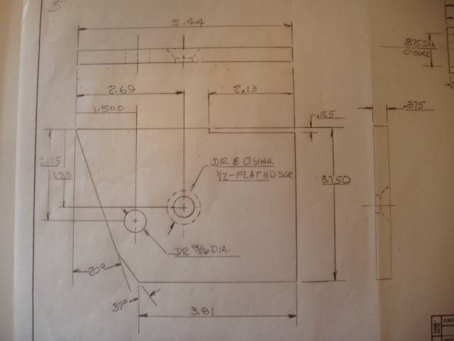
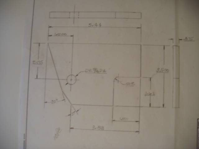
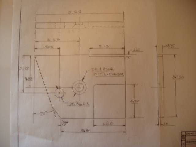
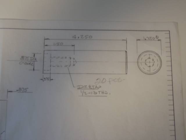
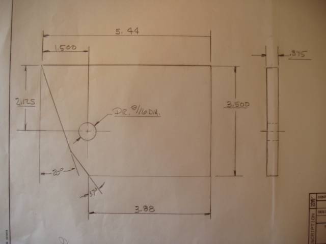
Engineering Drawings:
NOTE: I was just reviewing the prints on the parts and there is an incorrect dimension listed for both of the lower plates. The dimension listed for locating the 9/16" hole from the edge should be 2.25" and not 2.125". 2.125" is the correct dimension for both of the upper plates.
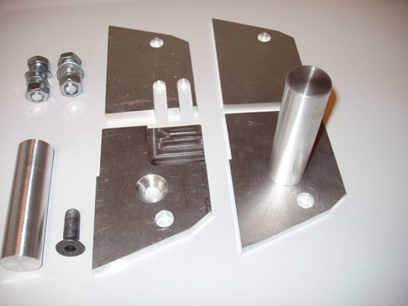
Frame extension plate upper LH
Frame extension plate lower LH
Extension pin (modified for being removable)
Frame extension plate upper RH
Frame extension plate lower RH