![]()
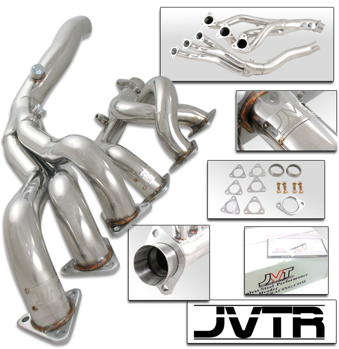
Installing BMW Z4 M-Coupe (S54) JVT
(eBay) Headers
The OE
exhaust manifold for US spec S54 BMW motors is different from other parts of
the world in that it contains primary cats that light off quicker and start
working earlier- we still have the same cats in the mid-pipe that everyone else
gets, kind of overkill.
SuperSprint
was one of the first companies to market an S54 header, some Chinese companies
took these and started producing copies in T304 stainless steel that make
headers significantly cheaper than the SS headers they emulate. JVT is reputed
to be the better fitting of these “eBay” headers but is no longer making these
for the S54 motor. I bought mine as they were shutting down production and was
able to get JVT Headers without the nameplate welded to the header- same flange
to work with OE head studs and same warranty. An example of an eBay header dyno
can be found at http://www.m3forum.net/m3forum/showthread.php?t=193538
I
purchased these JVT headers for $200, about $1500 cheaper than the SuperSprint
headers they copy. If I have any issues with them I will re-evaluate but
several guys on the M3 forums have run these for a while with no issues
post-installation……it seems all of the issues pop up during installation. Why
go cheap for my BMW? More out of curiosity based on M3 owners reviews, if I
have any issues I will just replace them with SuperSprint headers…..and if I
don’t have any issues I will have gotten out cheap.
You should
have software tuned for headers to get the max gains and to avoid a
check-engine-light….ESS is my drug of choice.
Standard
Disclaimer: ANY USE OF THIS INFORMATION
BY YOU IS AT YOUR OWN RISK.
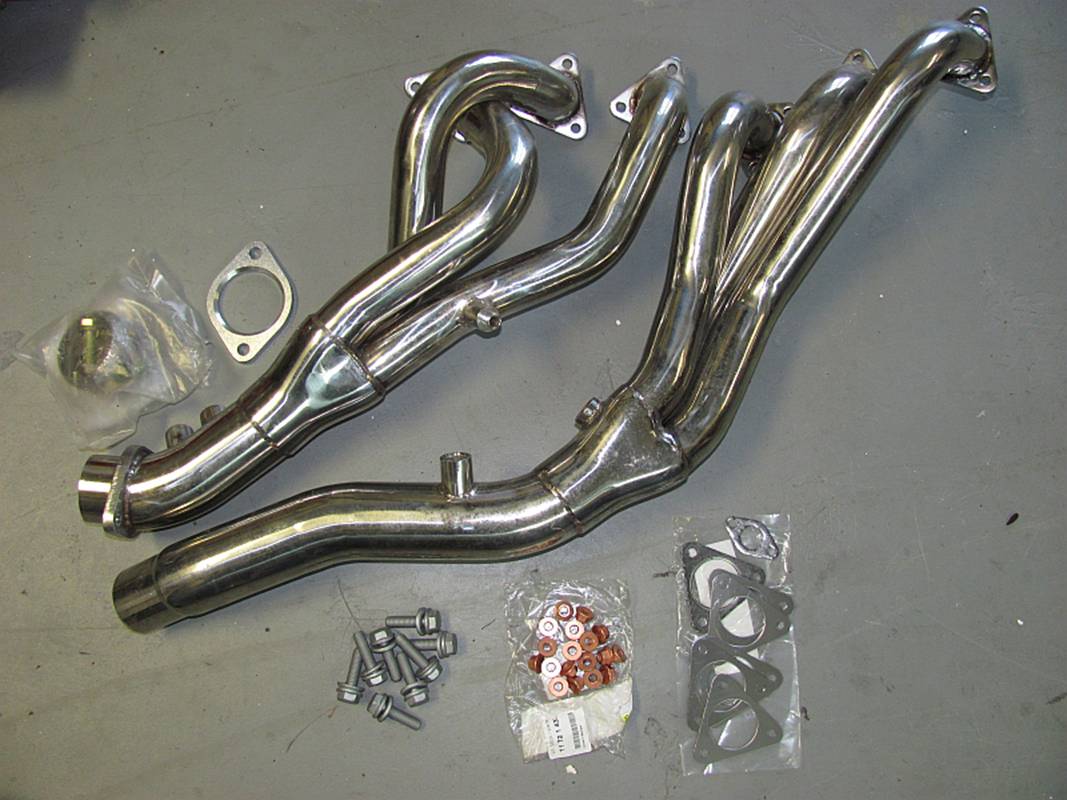
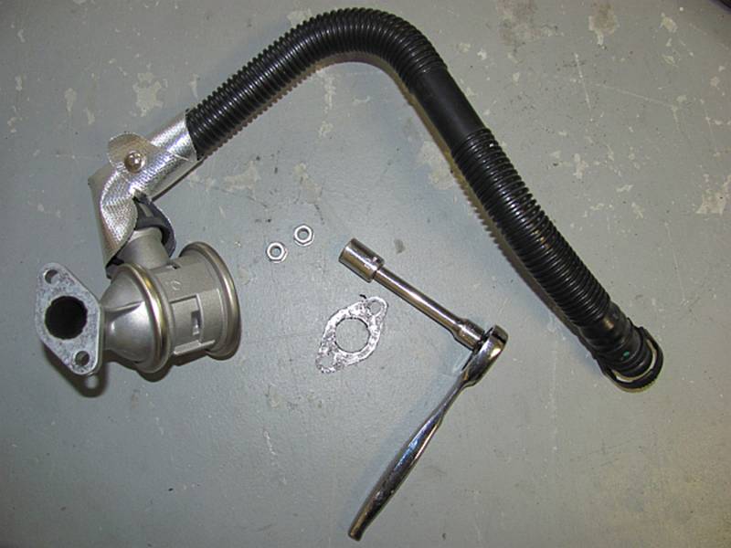
Sourcing Parts:
JVT
headers are NLA but are basically the same as the other S54 headers on eBay
sold for the M3. The hardware that comes with the header is cheap so most that have
installed these have opted to order OE hardware from Tischer (www.getbmwparts.com). Tischer sells
these as a kit, note that the current eBay header offerings have a thicker
flange than the JVT and will require E36 M3 studs in place of the S54 studs:
- 18 manifold studs
(P/N 07129900298) – I did not order these since mine were in good
condition with low miles.
- 18 manifold nuts
(P/N 11721437202) – These are really one-time use nuts so I ordered these.
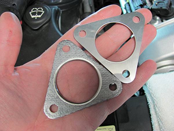
- 6 header
gaskets (P/N 11627830667) – These gaskets are a LOT thinner than the
header supplied gaskets and are required to use the OE studs.
- 1 air-pump valve gasket (P/N 11727505259) – This is like the header gaskets, one time use.
- 4 header to
exhaust bolts (P/N 11621318568) – I did
not order these and reused mine.
- 4 header to
exhaust nuts (P/N 18301317898) – I did
not order these and reused mine.
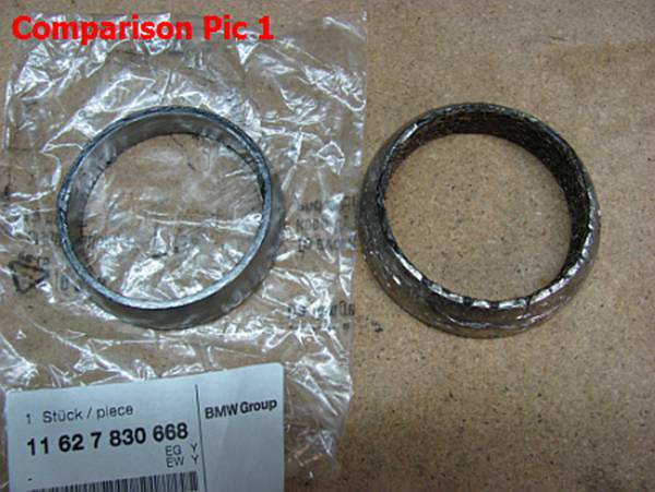
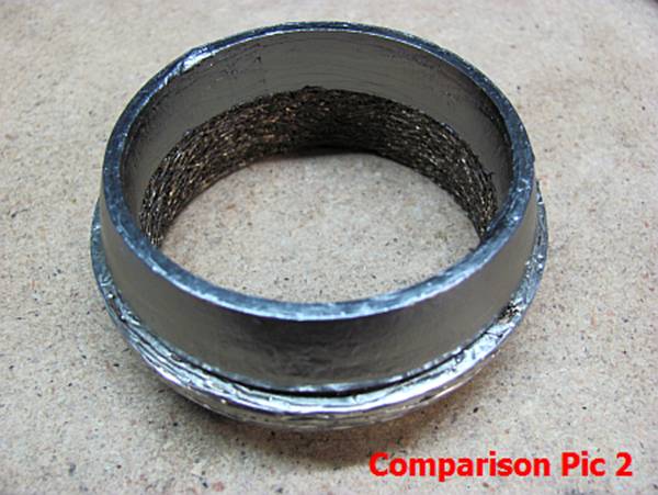
- 2
header to exhaust gaskets (P/N 11627830668) – I ended up ordering these
post installation; better fit than the supplied gaskets.
- 8 front axle
reinforcement plate bolts (P/N 31106772199) – These are torque-to-yield
bolts (aka one-time use) and are required.
Installation:
The E46 M3
forums have some DIY guides for these headers.
pal has a
write-up on his Z4M European header installation at http://www.zpost.com/forums/showthread.php?t=331906
that was helpful to
me.
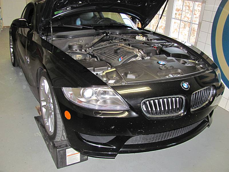
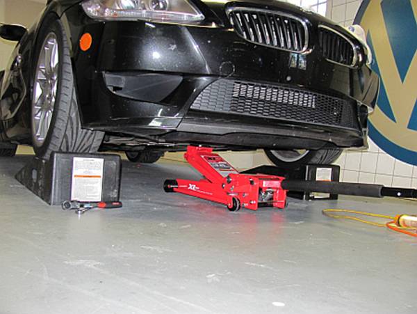
The car
needs to be up in the air, ideally so that the top and bottom of the engine
compartment can be accessed easily. I started off by driving my car up on to
ramps (and chocking rear wheels).
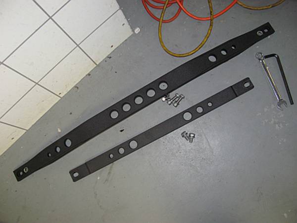
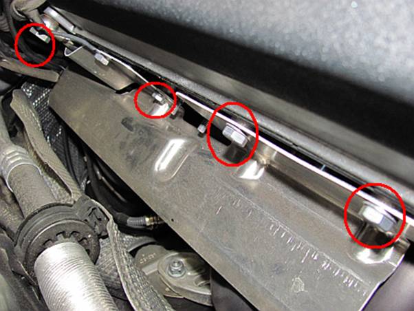
The strut
braces blocking access were then removed:
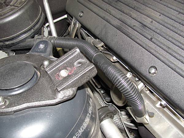
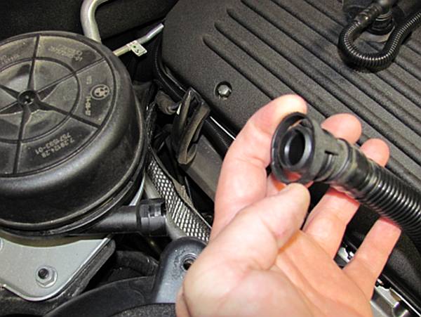
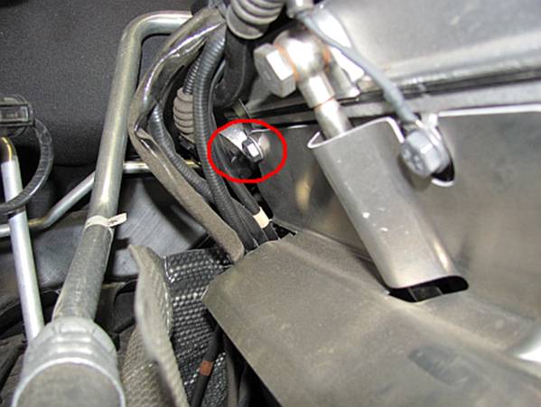
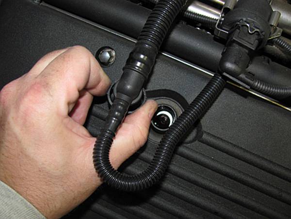
The air pump
valve and hose is removed. Pinch the plastic ring around the hose end and pull
to release. A 10mm socket with ratchet and extension can be used to remove the
two nuts that hold the air pump valve to the head. The gasket is also removed;
any residue it leaves on the head/valve is carefully cleaned off:
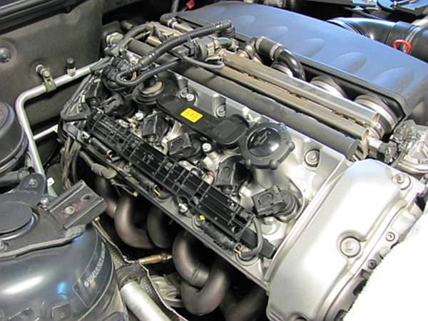
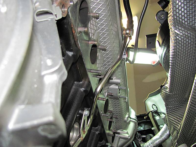
The upper
heat shield is removed. 3 bolts are removed using a 13mm socket (one is hiding
at the back under the wiring harnesses) and a single bolt beside the air pump
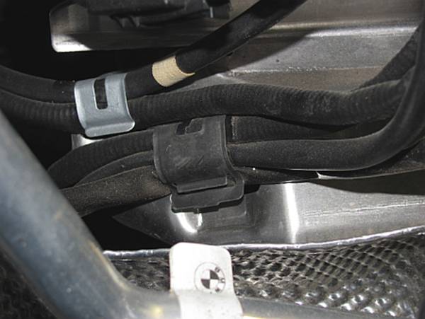
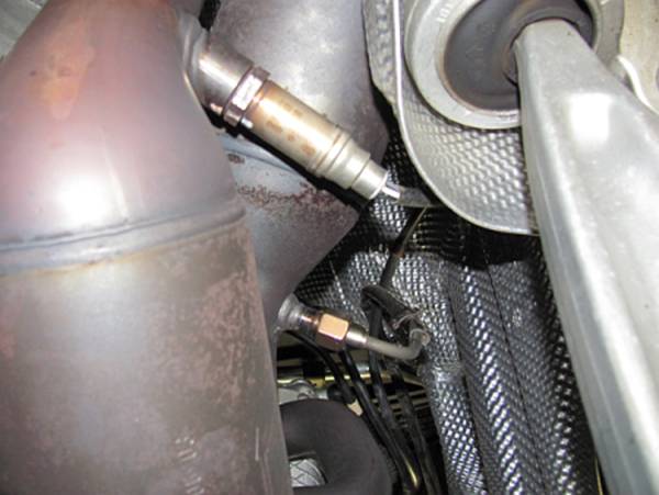
valve is removed using a 10mm socket. The wiring for the O2 and EGT sensors is
removed from the heat shield retainers at the back (lift up clip and pull
wiring free) and the heat shield is removed:
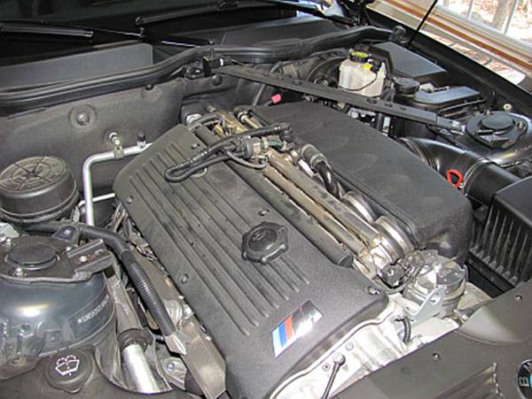
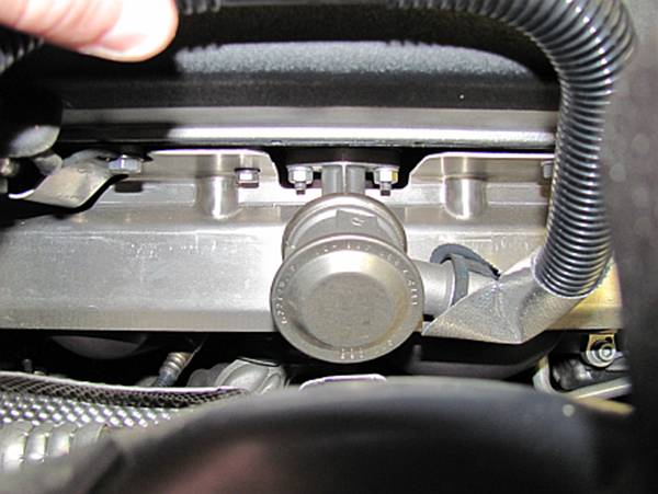
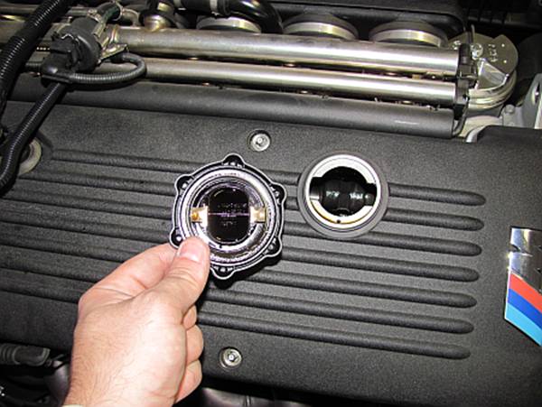
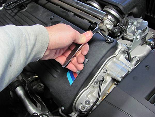
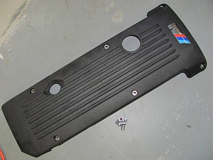
The
cylinder head plastic cover is removed. The oil cap and vent hose should be
removed first, then the six chrome nuts are removed using a 10mm socket. After
the cover is removed the oil cap is reinstalled:
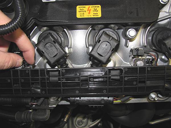
[OPTIONAL]
If the sensor plugs need to be accessed, the two retaining clips can be pressed
to turn over the plug/harness holder- I did not have to do anything with these
plugs but it may be required if you decide to relocate the O2 and EGT sensors
to the mid pipe as done HERE.
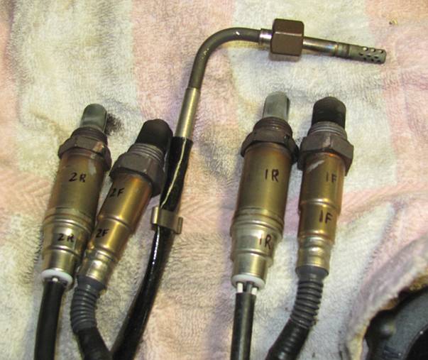
The plugs are labeled 1 for the Front/Bank 1/Section 1 post-cat O2 sensors, 2
for the Rear/Bank 2/Section2 post-cat O2 sensors. The pre-cat O2 sensor plugs
follow the same convention with labels and can be seen on the outside edge of
the plug/harness holder opposite their post-cat counterparts:
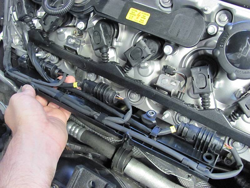
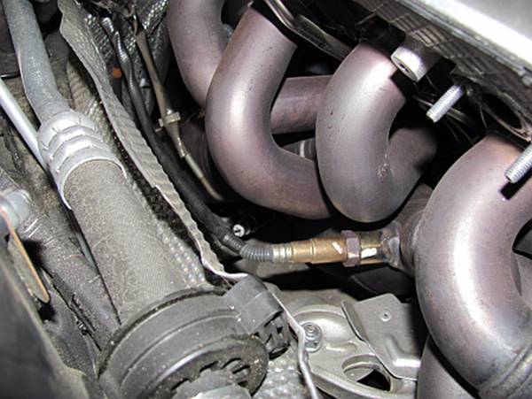
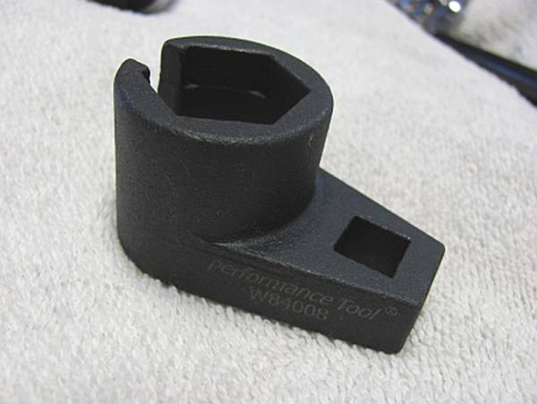
The O2 and EGT sensors are removed and labeled- it is CRITICAL that the O2 sensors go back
in the same position they were removed from. I broke down and bought an O2
sensor socket for this, it made the job really easy. Try not to twist the wires
as you remove and install the O2 sensors.
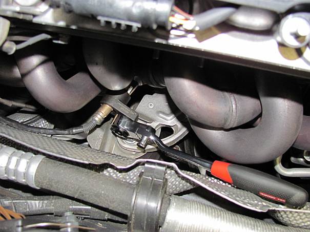
The O2
sensors on top were removed first. A large ratchet was used for the section 1
pre-cat sensor; a small ratchet was used for the section 1 post-cat sensor:
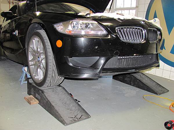
The remaining O2 sensors and EGT sensor were removed from below, but I needed a
little more room than ramps offered. A jack was used with the front/center jack
point to lift the car and jack stands were placed under the front jack points-
you can see I also flipped the ramps around to be there just in case (and I
like to hear people ask me how I got the car on ramps that way).
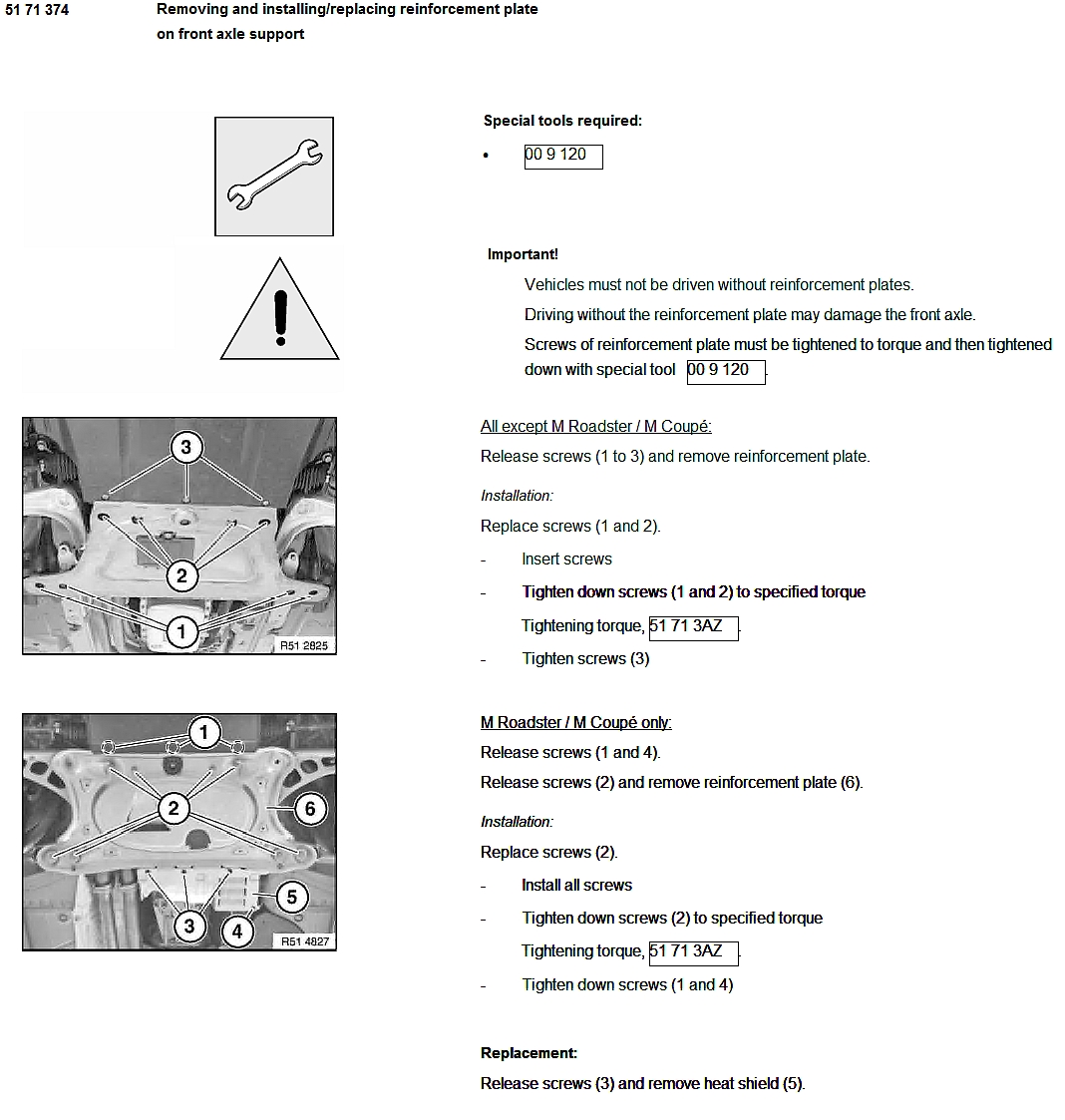
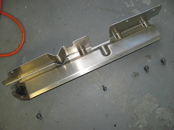
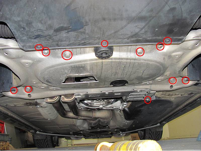
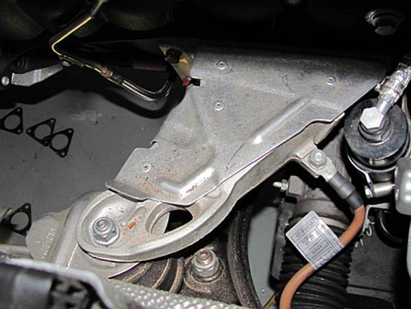
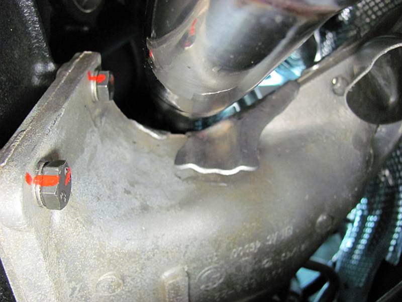
The front
axle reinforcement plate was removed, there are 3 screws in front that are
removed using an 8mm socket, one screw at the attached rear shield is removed
using a 10mm socket, and the 8 large bolts (one time use) are removed using a
16mm socket. After removal I placed it on the ground and pushed it towards the
back of the car and out of the way:
You can
see the O2/EGT sensors on the Section 2 are more accessible from below. I
removed all of the sensors before dropping the section1/2 but some have dropped
the section 2 to remove the O2 sensors. The O2 sensors were labeled for section
1 (front) or section 2 (rear) and with ‘F’ront for pre-cat and ‘R’ear for
post-cat, you can label these with whatever makes sense to you so that you can
get them back in the correct bung. All of the sensors were carefully placed on
a towel on top of the motor and out of the way- treat them carefully, they can
be expensive to replace:
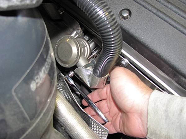
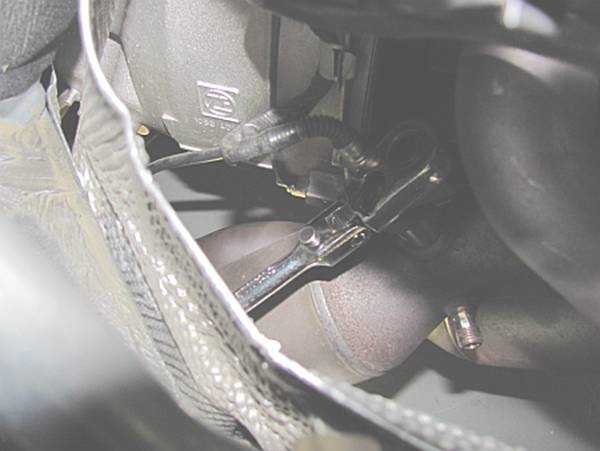
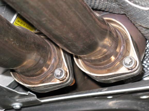
To
remove the four bolts connecting the section 1/2 to the mid-pipe I used an E12
external Torx socket (also called a reverse Torx) and a 14mm wrench:
After
reading all of the DIYs on the M3 forums I expected it to be painful to
remove/install the nuts holding the sections 1 and 2 to the head.
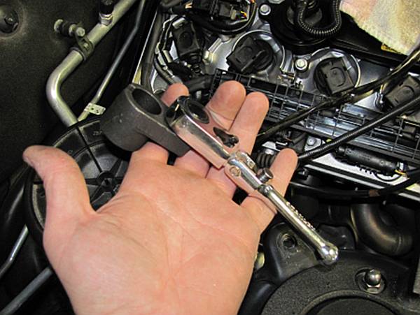
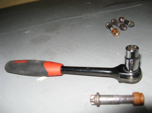
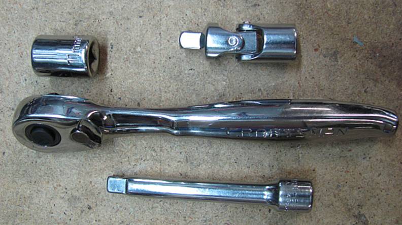
I
found that I only needed 5 tools to get the job done- a 1/4” ratchet, 11mm
socket, universal joint, and small extension. An 11mm closed end wrench was
used for 3 nuts on installation of the new headers. You will have to decide if
it is easier to access certain nuts from the top or bottom of the car during
removal and installation. The sections 1/2 are removed together from underneath
the car.
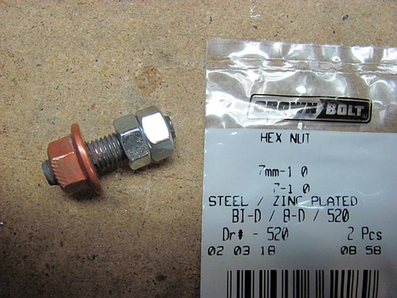
If
you do end up unscrewing the studs along with the header nuts, two tightened
and doubled up 7mm (1.0 pitch) nuts can be used to remove the header nut and
reinstall the stud in the head.
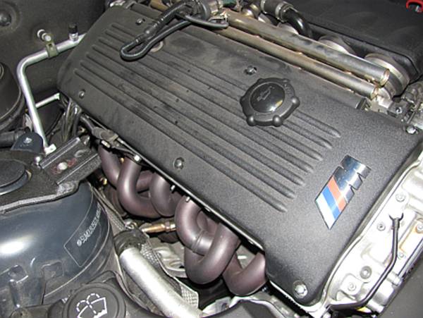
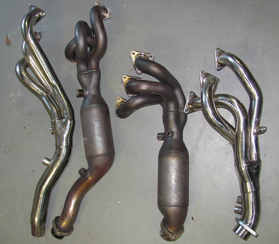
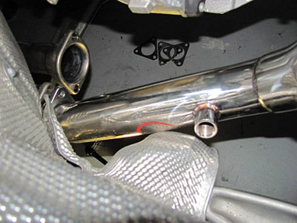
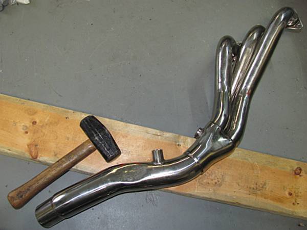
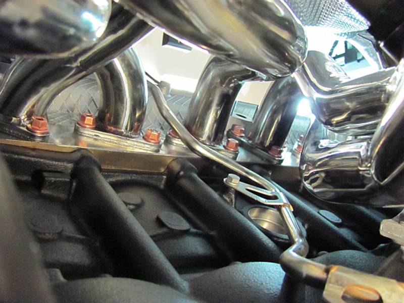
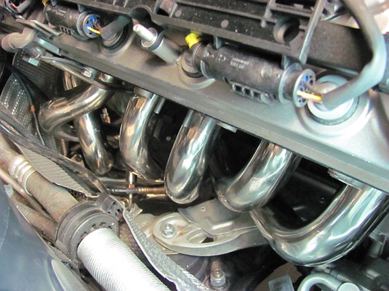
Comparison
pics- time to put the exhaust on a diet. The primaries on both the OE and
replacement headers measured at 1.5” OD. :
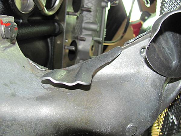
After
test fitting the section 1 header, I found two things that needed to be
addressed.
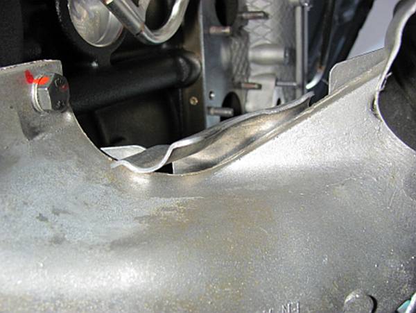
(1)
The JVT header, unlike the SuperSprint, does not have a relief in
the pipe to accommodate the FCAB (Front Control Arm Bushing)/ LCAB (Lower Control Arm Bushing). I marked this and used a 5-lb hammer to make
the relief indention- no worries with $200 headers.
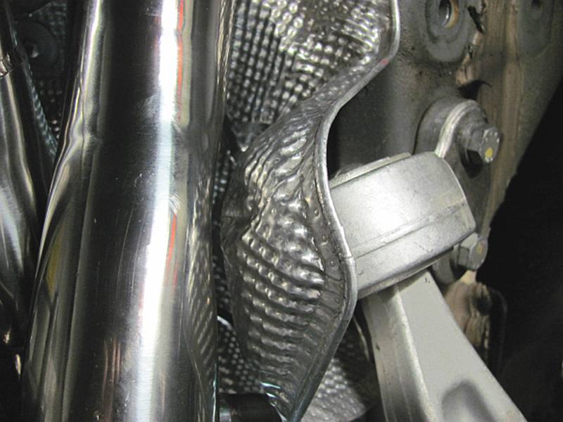
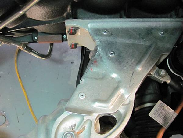
(2)
The heat shield on the motor mount protrudes just a little too far
and makes contact with the header; I used a ball-peen hammer to contour the
heat shield edges more closely to the mount to avoid this.
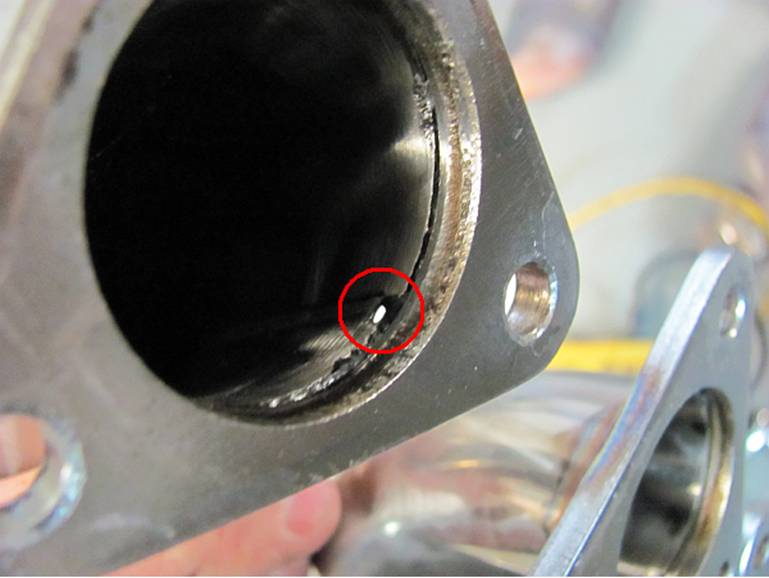
I
also found one pinhole in the section 1 header that required some TIG welding
to close up. I would not have wanted to find this after installation so if you
cheap out like me and go with Chinese headers, do your best to check the welds
before installing (a pressure test may be worthwhile for cracks/holes you can’t
see):
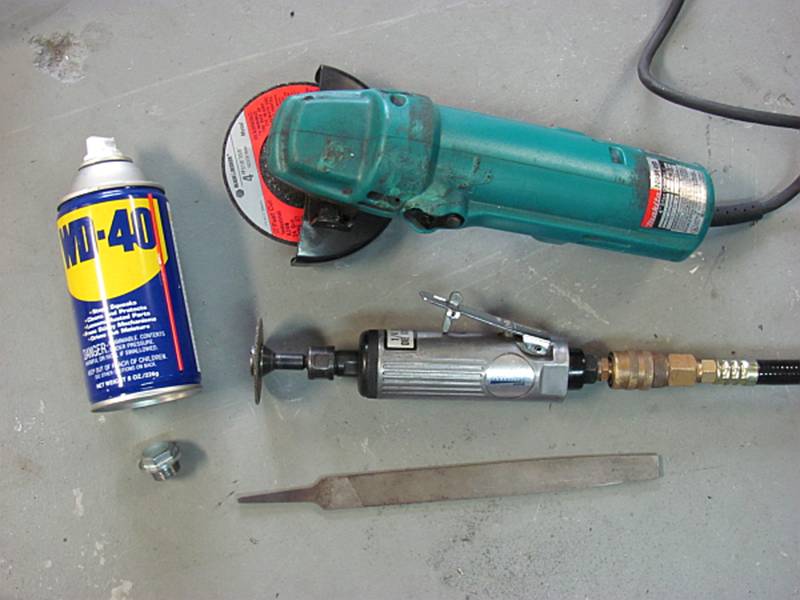
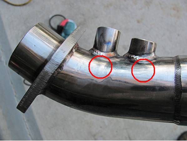
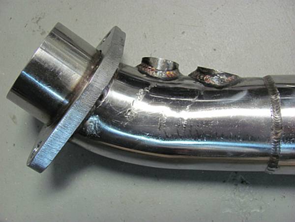
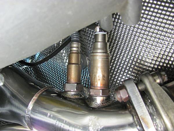
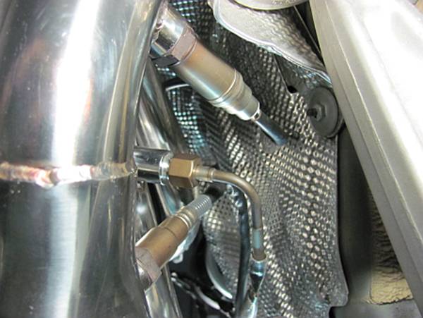
After
test fitting the section 2 header, it was obvious the O2 sensor bungs were in
the wrong place and the sensor would make contact with the transmission. If
they had moved them over about an inch there would have been no issues. I
decided to grind the bungs down but if I had it to do over I would have just
capped these off and had two more bungs welded next to them to use- using a die
grinder/cutoff wheel, grinder, and file to grind these down and then adjust
them until they were flat was painful. After grinding, I used the file and cap
bolt the headers were shipped with to finalize fit- WD40 works great to prevent
the cap bolt from stripping the threads and/or cross threading. Even after
these adjustments, the wiring for the post cat O2 sensor was still close to the
transmission (within ¼”) - I’ll keep an eye on it, but it should not matter
since the motor/transmission/headers move together:
The
headers are reinstalled the same way they were removed- together. The
header/head gaskets are installed with the shiny side towards the head and the gray/soft
side towards the header- spray gasket adhesive would have been useful here to
keep these in place on the head as the headers were positioned. Before
reinstalling the heat shield and other items on top, you may want to heat cycle
the headers 1-2 times and retighten the header nuts. There is a torque spec but
these nuts will have to be installed by feel for the most part, using a
1/4" ratchet it is hard to get into trouble but make sure they are hand
tight, not gorilla tight. Make sure the sensor wiring is routed as far away
from the headers as possible and clipped into the heat shield wire retainers.
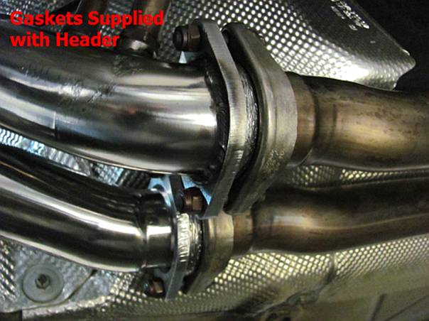
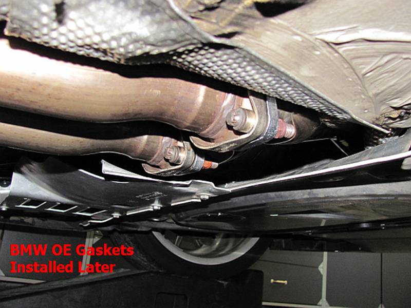
[EDIT] I
originally installed the supplied donut gaskets (header > mid-pipe) but
later installed OE gaskets. They fit better and allowed the flanges to clamp
better.
With
everything reinstalled, it is hard to see the headers but you will definitely
hear them. Not a lot louder but a bit more raspy and racy sounding. I don’t
have any exhaust leaks and the car feels a bit stronger, so far so good.
TIS
instructions below with torque specs for reinforcement plate installation, the
bolts are installed for the specified torque value and then another 90 degrees
of rotation: