
High Pressure Fuel Pump Install on a 2007
BMW 335i
The goal of AMS is to provide the highest
quality, best performing products available. By utilizing research and
development, and rigorous testing programs AMS will never compromise the
quality or performance of our products. In addition, AMS will only provide the
finest customer service offering only parts and advice that are in the best
interests of the customer. AMS was built on a foundation of integrity. This is
who we are; this is what you can count on.
A vehicle modified by the use of performance
parts may not meet the legal requirements for use on public roads. Federal and
state laws prohibit the removal, modification, or rendering inoperative of any
part or element of design affecting emissions or safety on motor vehicles used
for transporting persons or property on public streets or highways. Use or
installation of performance parts may adversely affect the drivability and
reliability of your vehicle, and may also affect or eliminate your insurance
coverage, factory warranty, and/or new OEM part warranty. Performance parts are
sold as-is without any warranty of any type. There is no warranty stated or
implied due to the stresses placed on your vehicle by performance parts and our
inability to monitor their use, tuning, or modification.
These instructions are provided as a guide
only as there are many variables that cannot be accounted for concerning your
particular vehicle, including but not limited to model year differences, model
differences, the presence of non-OEM parts, and modifications that may already
be or were previously installed. A basic knowledge of automotive parts and
systems is helpful but a better understanding of the parts and systems on your
particular vehicle may be required.
If you have any questions or issues at any
time during the installation of your AMS product(s) please call us for
technical assistance. The AMS tech line can be reached M-F, 9AM-PM Central time
at 847-709-0530 for AMS products only.
High pressure fuel pump install on a 2007
BMW 335i
Tools Needed:
•
8mm nut driver or ¼” socket
•
Flat head screwdriver
•
6mm nut driver or ¼” socket (above flathead can be used in its
place)
•
5mm Allen wrench
•
3/8” 10mm socket with 4-5” Extension
•
17mm” Wrench (open ended)
•
3/8” 11mm socket also used with 4-5” Extension
•
3/8” E12 Reverse Torx socket with 1” 3/8” Extension
•
Torx T-30 Socket or wrench
•
5mm Allen wrench cut down to 3.5” (you can read about this later)
•
¼” 5mm Socket (deep)
•
¼” Ratchet wrench
•
3/8” Ratchet wrench
Step one:
Disconnect the battery. This is very important and should not be overlooked.
Anytime you are working with fuel the last thing you want is any opportunity
for a spark.
You can locate your battery in the trunk
behind the passenger side fender. Simply remove the access panel by turning the
black knob 90 degrees and pull the panel out of the way. Using the 10mm socket,
extension and 3/8” ratchet loosen the negative battery terminal. This
terminal will be the one closest to the rear of the car. Once it is loose
remove the negative wire from the terminal and place it away from any metal. It
should rest comfortably on the center of the battery.
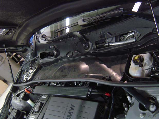
Step two:
Step two involves removing the in cabin Air
cleaner and cowl to gain access to the entire engine bay.
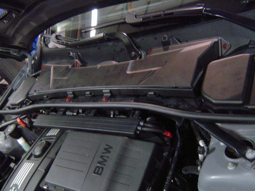
First remove the 6 8mm screws that hold down
the in cabin air cleaner. This can be done with an 8mm nut driver or a
¼” 8mm socket. The screws in question are circled below in red
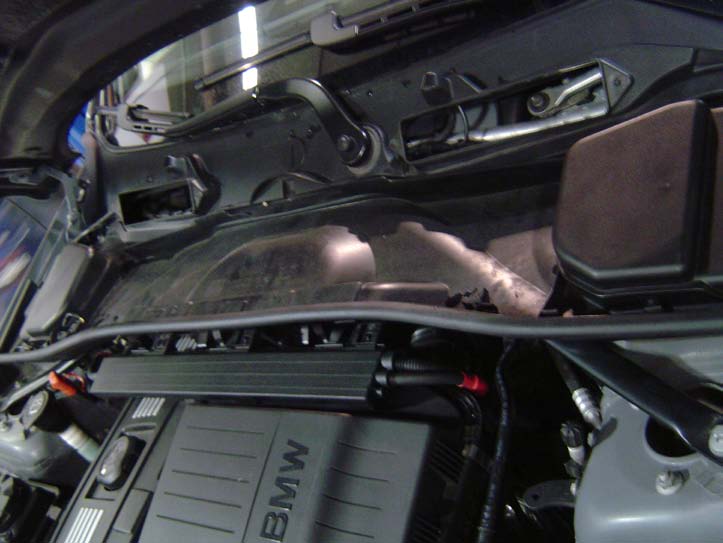
Once removed the air cleaner has been removed
the cowl should look like this:
Next we need to remove the two access panel
covers on either side of the cowl. The driver side covers the brake fluid
reservoir and is very easy to remove. Simply pull gently back on either tab
that secures cover and remove it. There are also a few rubber stays that must
be moved out of the way that look like this:
The driver’s side is a little trickier.
First there is a sensor that sits on your cowl the must be disconnected from
its base so the cowl can be removed. To do this use a pick or thin object
(paper clip should work) to depress the lock pin and rotate it so it slides out
of its housing. Then just pull up on the two clips that secure it to the cowl
and rest it out of harm’s way. The sensor should look like this:
Now that you have both covers off the only
thing left to remove is cowl cover itself.
Ignore the USB cable shown on my
driver’s side. That is for the CP-E standback we are testing. Your car
will not have this unless you have equipped it the same way.
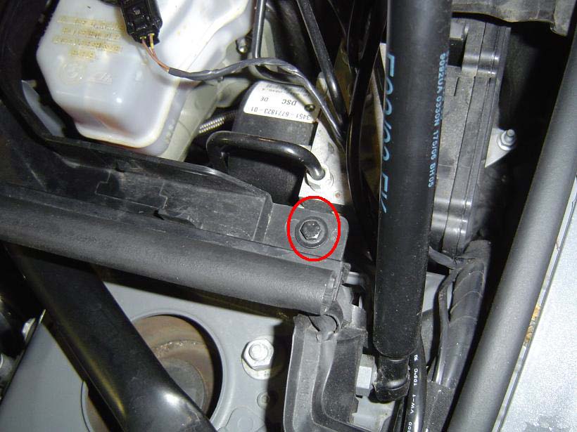
First we need to remove the two 8mm screws
that secure the cowl to the chassis. There is one on either side just near each
end of the cowl weather stripping
Once both of those are off we need to unclip
the wiring looms at the front of the cowl
To do this use the flat head screw driver to
depress all the clips. This can be a bit tedious but take your time and try not
to break the clips. There are three that hold each loom to the cowl. Once this
is done simply remove the cowl cover.
Step Three:
This step involves removing the air box,
upper intercooler pipe and diverter valves.
Now depending on what is done to your car
(Dual cones, Upper IC pipe, Upgraded Diverter valves / blow off valves) this
step might vary. The point is that these pieces need to be removed.
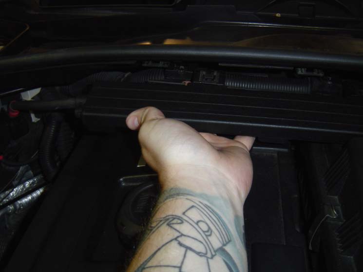
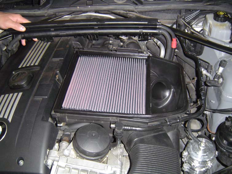
First we need to remove the air box. This is
pretty straight forward. First remove the air box lid and panel filter
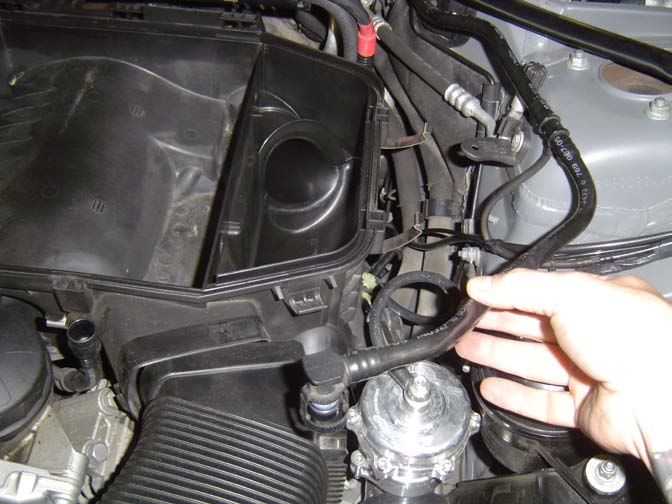
Next we need to do is to remove the brake
master cylinder vacuum line. This is very easy. Simple squeeze both ends of the
clip and pull. You might hear some air escape if the car was just run not that
long ago. This is normal. Once off you can unclip it from the air box and move
it out of the way.
.
Now we need to disconnect both turbo air
inlet tubes from the air box and the fresh air scoop from the box as well.
Again very simple
First locate the two air inlet tubes near the
top and bottom of the air box. Each tube is secured using a worm gear hose
clamp. This can be loosened using a 6mm nut driver or a simple flat head screw
driver. Once loosened you should be able to muscle the tubes off of the air
box.
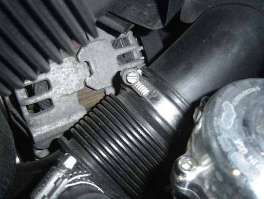
Here is the top tube shown with the worm gear
clamp:
And here is the bottom tube also shown with
the clamp:
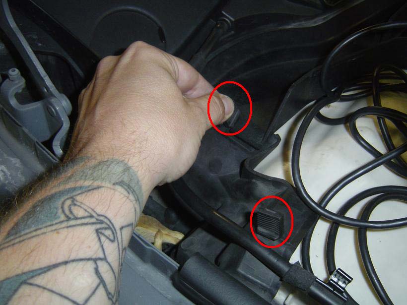
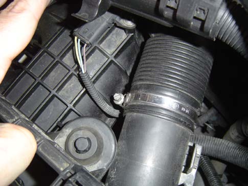
Now we need to disconnect the fresh air tube near
the front of the air box. This is held on by two small clips on either side of
the tube. You should be able to squeeze the tube to remove it from its clips
but you might need some very gentle coercing from a flat head screwdriver.
You can see the clip on the passenger side
pictures below
Once you have detached/loosened the turbo air
inlet tubes and fresh air scoop from the air box we can now remove the air box.
There are three rubber grommets that hold the air box to the intake manifold.
There is no real secret to removing them other then pulling, wiggling and just
generally working it loose. Once removed place the air box somewhere where it will
be out of your way until you are ready to reinstall it.
Now that the air box is out of the way
it’s time for the upper intercooler pipe. Now I have a CP-E upper
intercooler pipe with a Tial blow off valve so it was a little easier to
remove. If you have a stock setup or stock with forge valves I will walk you
through the removal as best I can remember. Because I do not have the stock
setup on my car there will be no pictures for this section.
First we need to loosen the 6mm worm gear
hose clamp that attaches the upper intercooler pipe to the lower portion of the
upper intercooler pipe. Again this can be done with a 6mm nut driver or a flat
head screwdriver. Loosen this clamp so it spins freely.
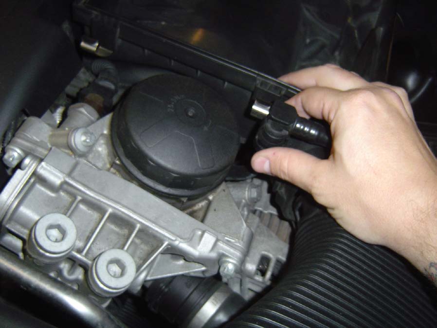
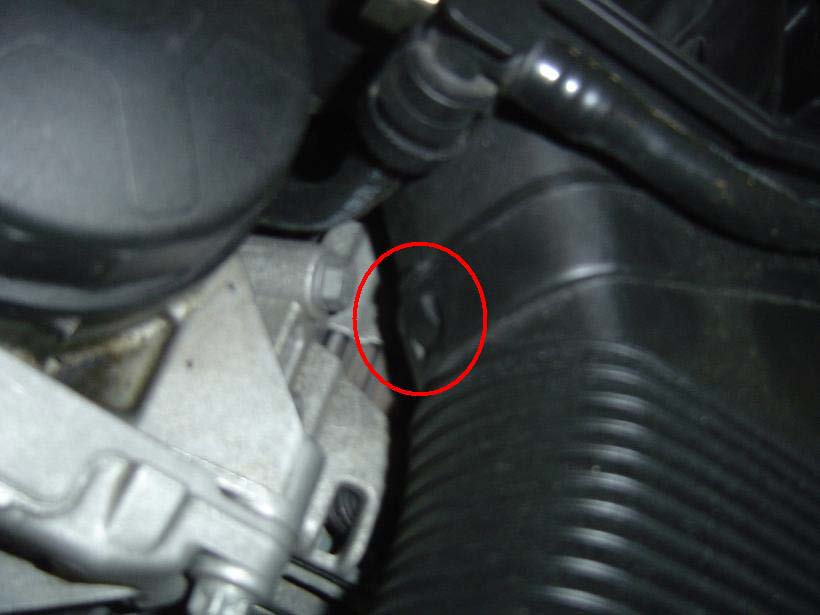
Now let’s disconnect the vacuum line
from the diverter valves. The easiest way to do this is by disconnecting the
vacuum line at the intake manifold. Using your hand follow the line as it
terminates as the intake manifold. This is where you will remove the line that
feeds both valves. BE
CAREFUL the vacuum nipple on the
intake manifold is plastic and can break off if you use too much force. Gently
twist and pull on the vacuum line until it comes off.
Now we are ready to remove the diverter
valves from the car. This can be done by turning the white/grey clip 90 degrees
until it unlocks from its receiver tube. Do this to all four connections and
remove your diverter valves
Now we need to remove the upper intercooler
pipe from the throttle body. This is pretty easy. There is a large C-clip that
locks the upper pipe to the throttle body. Using a small flat head pry it up a
bit and pull back on the clip. It doesn’t need to come off just pulled
back enough so it’s not resting in its groove anymore.
The pipe might not come off smoothly. More
than likely you are going to need to wiggle it a bit before she comes loose.
Only a couple more steps and we can remove this pipe.
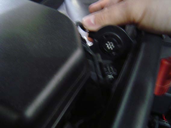
There is a MAP sensor at back of the upper
intercooler pipe right where it bends into the throttle body. This harness is a
bit tricky to get at and it’s easy to break. Some suggest using a USB
cable end to gently pull the tab away from the harness and slide out the
connector. I have always used my fingernail on my thumb and been ok but I can
see how this might be painful it if slipped. You might want to try using the
USB cable end to remove it
Now that that is off you should be able to
remove the upper intercooler pipe.
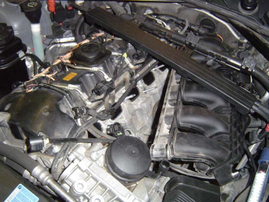
Now we have exposed the HPFP!
So how do we get this little guy out? Time to
move on to step 4
Step 4:
This step is really all about removing items
so we can access the three 5mm bolts that attach the fuel pump and the two fuel
lines. I suppose if a person were a contortionist or really creative you might
not need to remove the next two items but I like the take the path of least
resistance.
First we need to remove the throttle body
from the intake manifold. This will just give us more room to work and get at
two of the three bolts and both fuel lines.
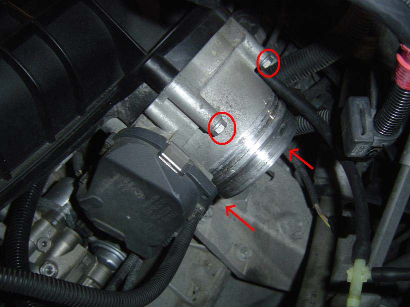
The throttle body is held on by four 10mm
bolts. Use a 3/8” 10mm socket, extension and ratchet to remove these four
bolts. They are pretty easy to get at now that we have the intake and
intercooler pipe out of the way.
I have outlined the 4 10mm bolts below:
Once they are disconnected remove the
throttle body from the intake manifold. You do not need to remove it from the
engine bay. Just push it out of the way so it makes it easier to work.
We can now access about 70% of what we need
to on the pump. The other 30% comes from detaching the intake manifold from the
head. This step I honestly tried to avoid but in the end it was much easier to
do this then to try and monkey my way to the back side of the fuel pump.
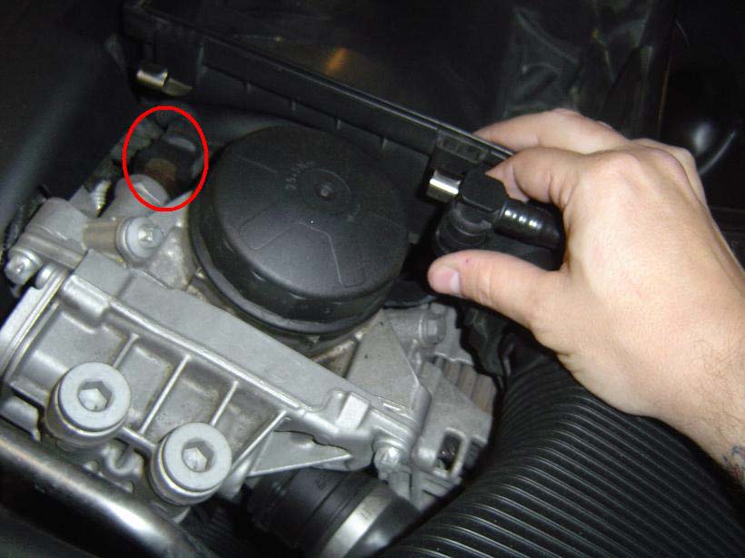
Disconnecting the intake manifold is not that difficult actually. Again we are
not removing it we are just unbolting it so we can get in beneath it. First
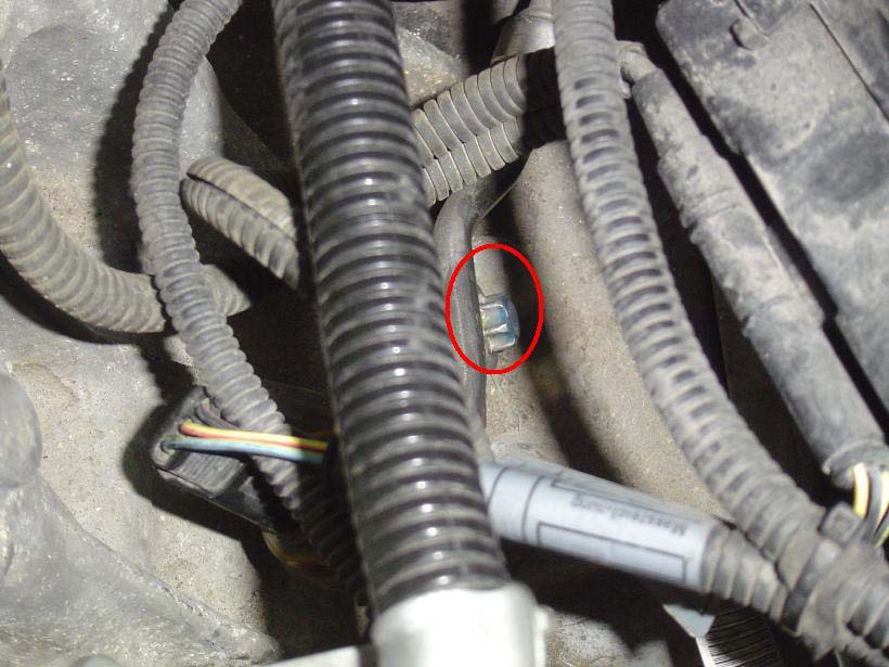
there is a sensor at the top of the engine just behind the fuel filter cover.
To remove the harness place your finger underneath the sensor and depress the
metal clip and slide the harness off.
I have circled the harness in question below:
Also to make things easier we are going to
remove the engine cover. This is really easy and is only held on by four 5mm Allen
bolts (two at the front, two at the back) remove these and slide off the engine
cover.
There were also two more harness at the top
of the engine (injector harness’) that I disconnected as well as they
looked like they would get in the way of sliding off the intake manifold. I
apologize but I did not take pictures of this. They are two identical harnesses
right at the top of the engine. The wire leads wrap around the edge of the
intake manifold making it hard to get to the intake manifold bolt closest to
the front of the car.
Now that we have that done we can start
removing the 7 11mm bolts /nuts that hold the intake manifold to the head. Use
the 3/8” 11mm socket, extension and ratchet for this. They are all nuts
with the exception of the one bolt that sits closest to the oil filter. Lastly
I would remove the harness that connects the map sensor on the intake manifold.
This is on the top of the manifold at the back of the engine. Again this is a
delicate clip and you might want to use that USB cable end to remove it. I
again just used my thumb nail.
Now we can pull the intake manifold away from
the head. Really you should only need to pull it away this much:
Now we can access 100% of the pump.
Step 5:
It’s time to remove and replace the
pump
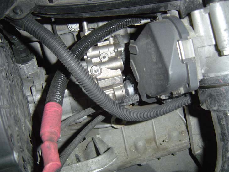
As you can see on your new pump there are
three bolts that hold it to the engine. The two closest to the driver’s
side are the easy ones to get it. It’s that back one facing the engine
that caused us to remove the intake manifold to get at it.
First unclip the harness on the right side of
the pump. This should be very easy to remove by simply squeezing the harness

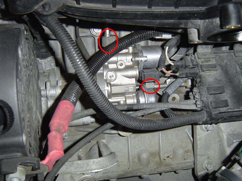
Next crack loose the two 17mm compression
fittings on the fuel lines. One is on the top of the pump and one on the right
side. Use that 17mm open ended wrench to loosen these. Make sure to completely
loosen them so the lines can be removed from the pump in the upcoming steps.
Now we need to remove those three bolts that
hold the fuel pump to the engine. These are all 5mm Allen bolts. The front two
can be accessed pretty easily with just a simple Allen wrench.
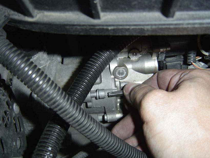
The last bolt is the hard one and honestly
the hardest part of the job. It’s situated between the pump and the
block. To get at it you will need some patience and some specific tools.
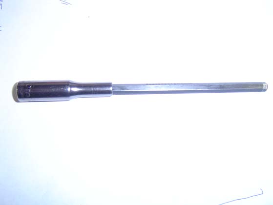
Now I had a really hard time finding a tool
that would fit in that space. You need to slide the Allen wrench behind the
pump. Too short and it will hit the pump and not reach the screw. Too long and
it will hit the fuel sensor on the fuel feed line. This is what I came up with
that worked well for me.
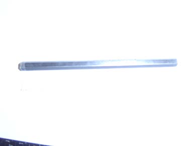
First I took a 5mm Allen wrench and cut it to
3.5” in length
Next I took a 1/4" 5mm socket and slid
the cut section into it
Now I just used a simple ¼”
ratchet and got to that back bolt pretty effortlessly. Once you get it cracked
loose you will most likely need to slowly back it out the rest of the way with
your fingers.
Now in order to get the pump out we need to
pull it away from the engine. The fuel lines are hard lines and are braced to
the block. We need to remove these braces so we can move the fuel lines out of
the way and remove the pump.
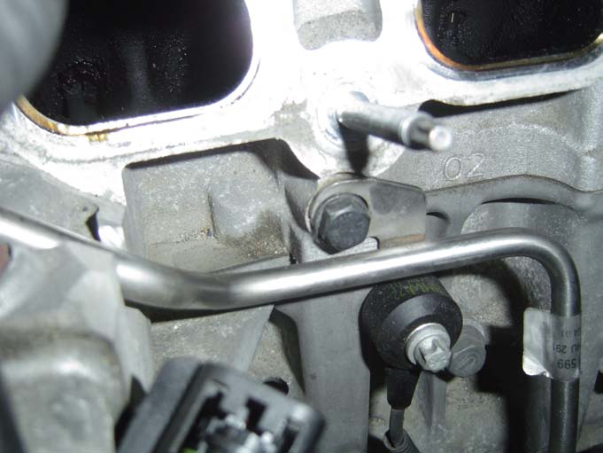
The first is pretty easy to get at and is
right above the pump. Just use an 11mm socket to remove this bolt
The second one is a little harder to get at
and needs a special E12 Reverse Torx to get it out. I used a 3/8” E12
reverse Torx bit, 1” extension and ratchet.
Now pull away the top line so you can
disconnect the line from the pump. The lower line is not a completely hard line
so once you remove that E12 Reverse torque fitting it should pull off the pump
pretty easy.
Now we just need to slide the pump off. As
you do this oil will spill onto the block from the housing. Just be sure to
clean it up before you reinstall the new pump.
Some fuel will spill as well but it’s a
very small amount. Just wipe it up with a rag if it doesn’t evaporate
before you do.
Hold the pump in the air and swear profusely!
To reinstall just follow the same steps in
reverse order. Make sure to snug up those fuel compression fittings. 3000 psi
can be messy if it leaks. Be careful when tightening the intake manifold and
throttle body. You don’t need to torque the hell out of these. Remember
it’s plastic and will break if you over do it.
When you start the car for the first time
it’s going to take a while to crank. That normal as the pump needs to
build fuel pressure. From there on out it should fire up really quick though.
Hopefully you won’t have to do this
again but if you keep the car long enough…chances are you will ![]()