![]()

Oil Cooler Upgrade Install Guide
CAUTION: Before beginning
please make sure that the engine is completely cold. Hot engine will have extremely
hot oil and components leading to the danger of being burned. Install at your
own risk. Not recommended for novice installers. I have updated this document that
Vince/VKM put together with some comments from my installation (in blue),
marked up existing pictures with red lines, and replaced some pics with my
pictures. My car is an E92 (Coupe) so this may have been why there were some
slight differences in my installation. If in doubt, compare this to the
original pdf document from VKM as it may be more applicable to your
installation. Bill
Tools needed for install:
13mm, 10mm, 8mm, and 6mm socket wrenches with
extension
T20 Torx driver
T20H Torx wrench
7/8” stubby wrench
Adjustable
Wrench (8” or 200mm length)
17/64” drill bit
Ruler
Dremel or similar cutting
tool
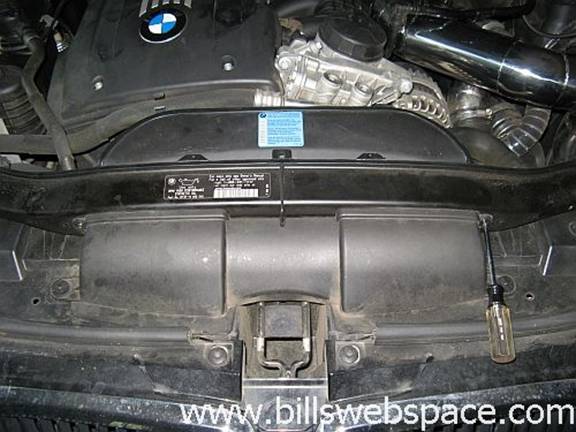
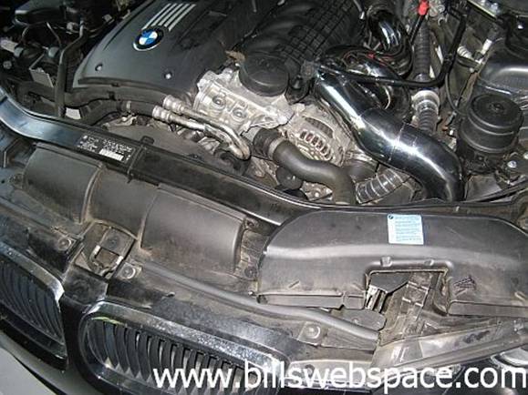
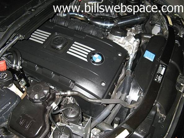
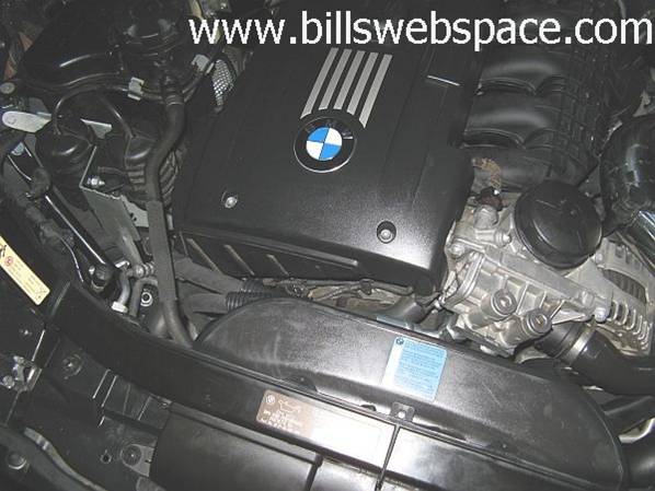
STEP 1: Remove air duct screws using a T20 Torx driver
(one on either side) and
disconnect air intake piping so that you can have room to access the oil cooler
thermostat housing.
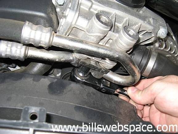
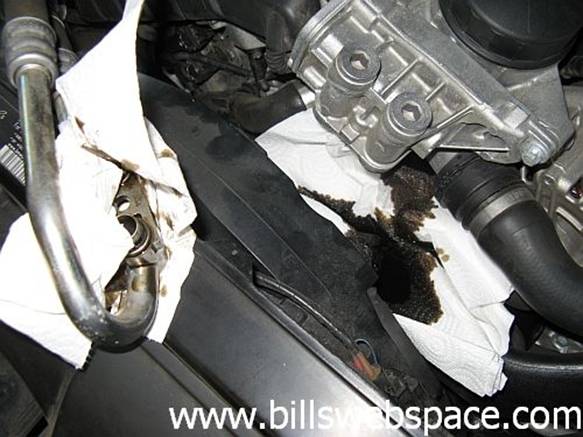
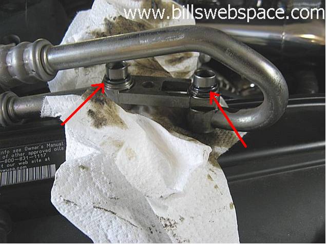
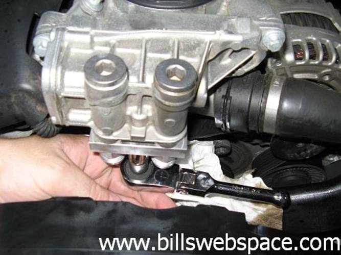
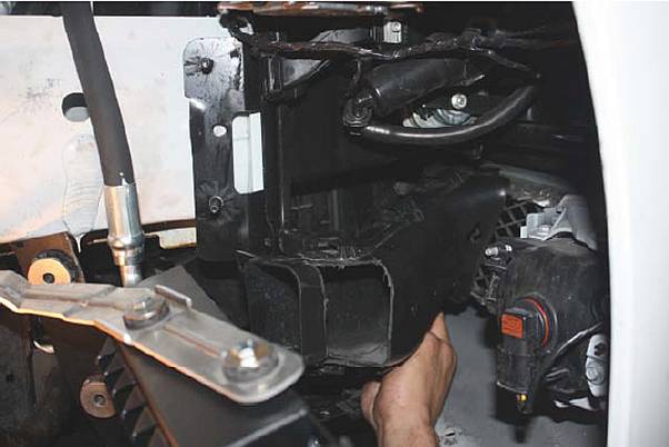
STEP 2: Using a 13mm socket wrench remove
the bolt that holds the oil cooler lines into the thermostat housing. Please
place a container under the thermostat as it contains oil. I used a small
¼” flex head ratchet with a regular 13mm socket, be careful that
no oil contaminates the serpentine belt located under and to the rear of the
oil filter housing.
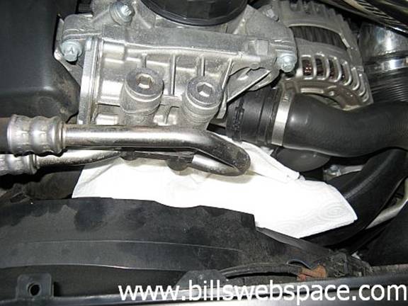
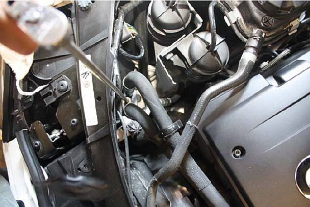
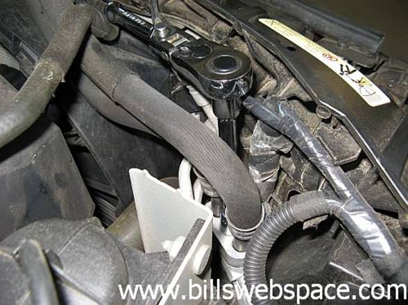
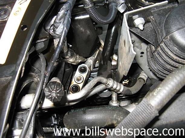
STEP 3: Using a 13mm socket wrench with
extension, remove the screw on the other end of the oil lines. Note: Place a container under the oil fitting because the
lines will contain oil (a decent amount of oil,
more than enough to make a huge mess). Try to have the container lined up and
be fast, dumping oil takes no time at all
![]()
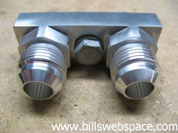
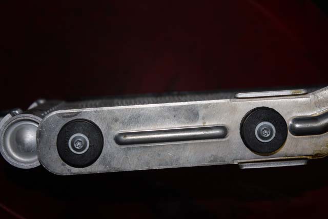
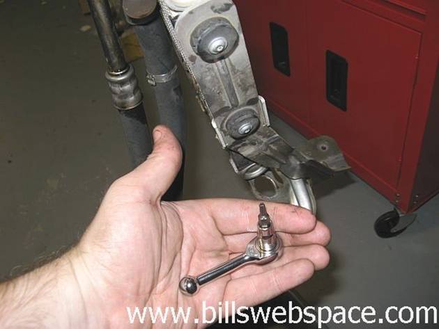
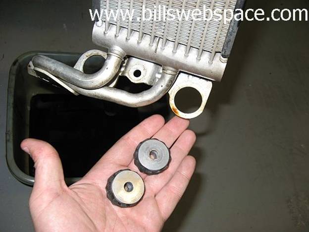
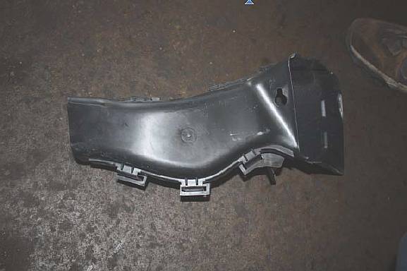
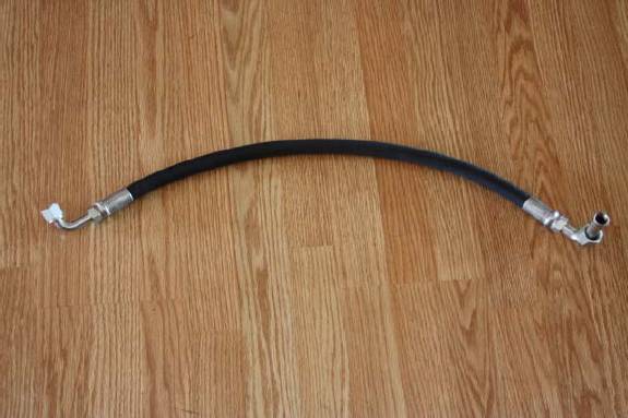
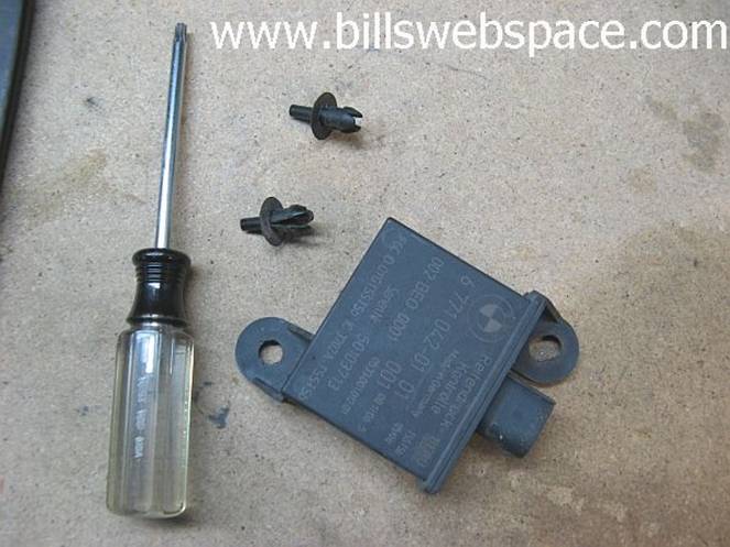
STEP 4: Locate the thermostat housing
adaptor provided in your V K Motorwerks oil cooler upgrade kit. It will look like
the part shown below:
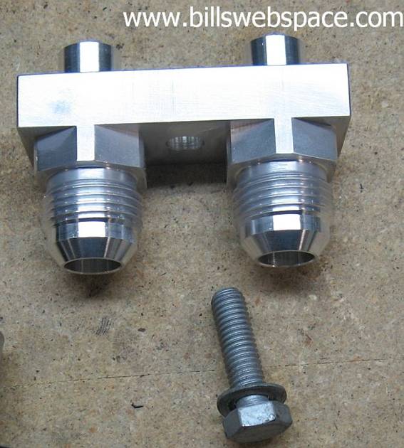
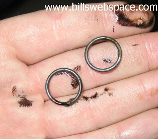
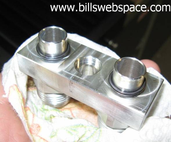
Step 5: Remove the two O-Ring seals from the OE
thermostat hoses and install them on the VK adapter. Using the bolt
that you previously removed from the thermostat, attach the V K Motorwerks
adaptor to the thermostat housing. You may use some grease to help
lubricate the adaptor. I found that the bolt area on the adapter is tight, a narrow wall
socket is required and my ¼” 13mm socket would not work. My
1/8” 13mm socket worked fine with an adapter (also helped as an
extension) using my ¼” ratchet.
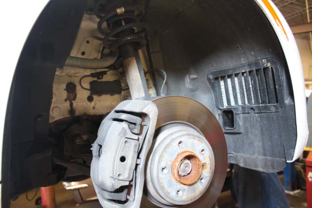
Step 6: Lift your car using a jack and jack
stands and remove your
right front
wheel to access the
wheel liner bolts.
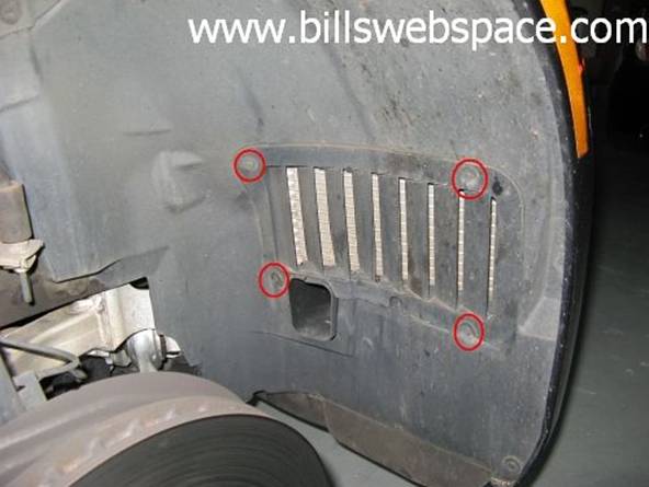
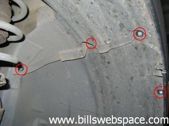
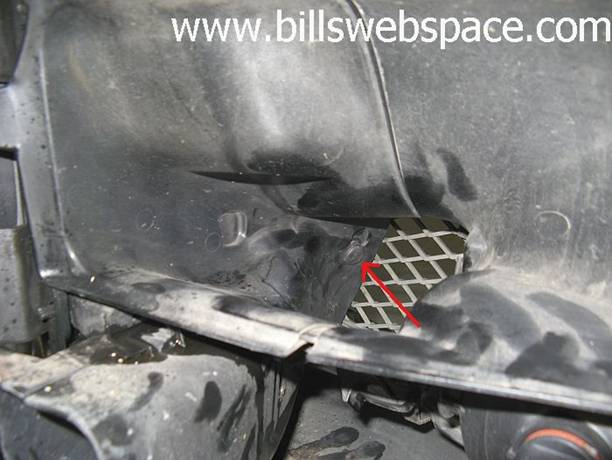
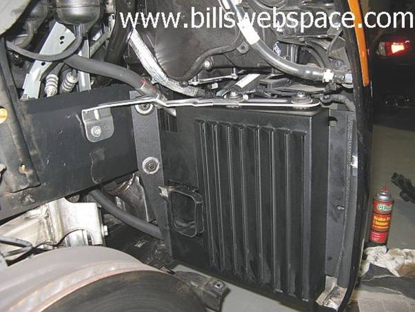
Step 7: With the 8mm wrench remove all the
bolts holding the wheel well cover in place. Only the lower left screw on the vent
retains the fender liner but its easy now to get the other three as well. Three
more screws in the top of the liner and three screws down the side are removed.
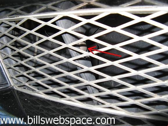
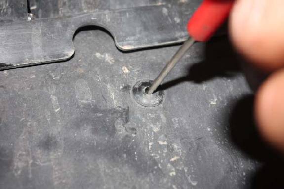
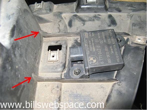
One plastic nut is removed using a 10mm socket or wrench. Five screws are
removed from underneath, some are hiding unless you are looking straight up at
them, specifically the one with the arrow in the picture below.
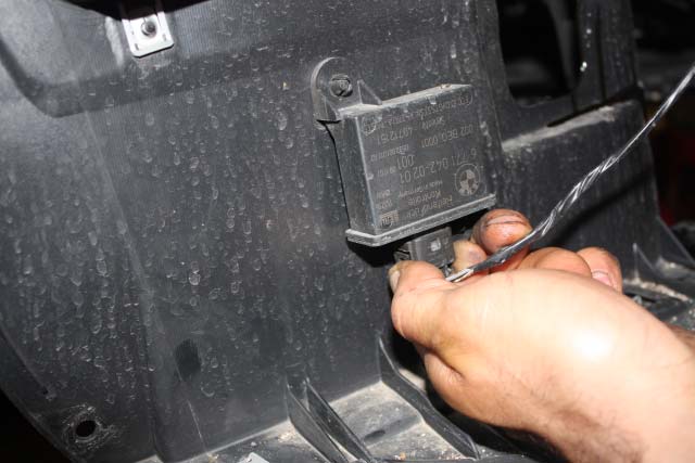
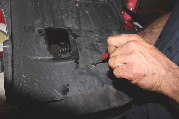
Caution: pull off the
wheel well liner SLOWLY…there is a Tire Pressure Monitoring (TPM) sensor
attached to the rear of the liner. Simply push the tabs together and the plug
should slide out. Do not use excessive force.
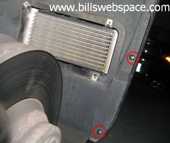
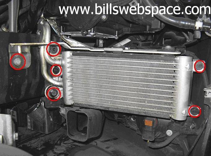
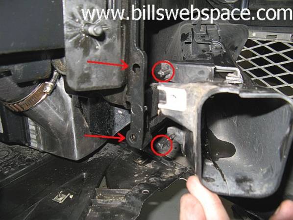
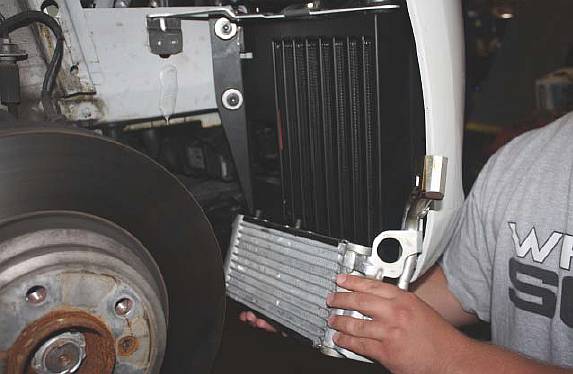
Step 8: Remove the screws and bolts on
both sides of the cooler. Please keep the cooler straight when you remove it
since it will be filled with oil. The three smaller screws (two on one side, one
on the other) require an 8mm socket, the single bracket screw requires a 10mm
socket, and the two nuts require a 13mm socket.
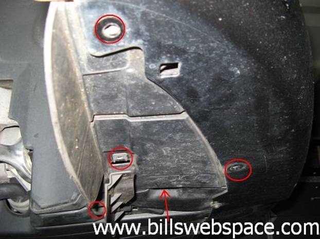
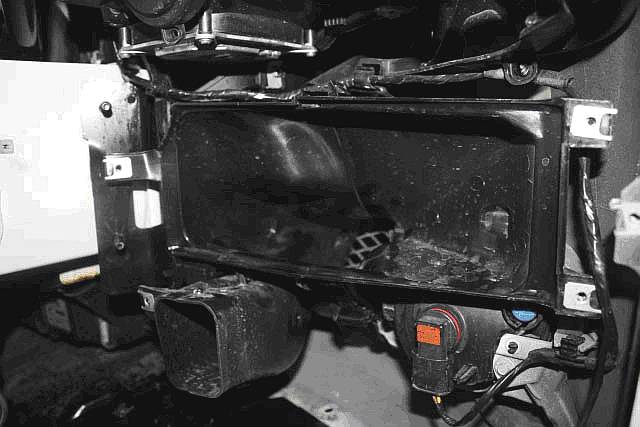
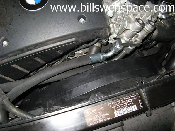
Step 9: Remove the air vent that is behind
the OEM oil cooler by loosening the tab inside the oil cooler air vent and
pulling up. The
rubber piece that holds the brake duct and the intercooler duct together in the
front can be pushed through and out from the front grill on the brake duct side
using a screwdriver so that they can be removed seperately.
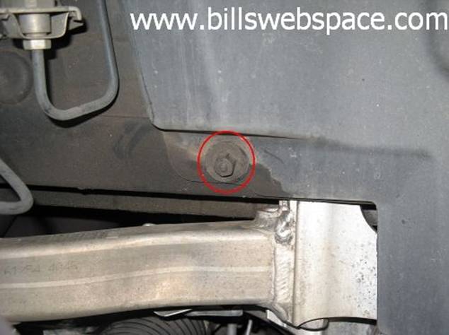
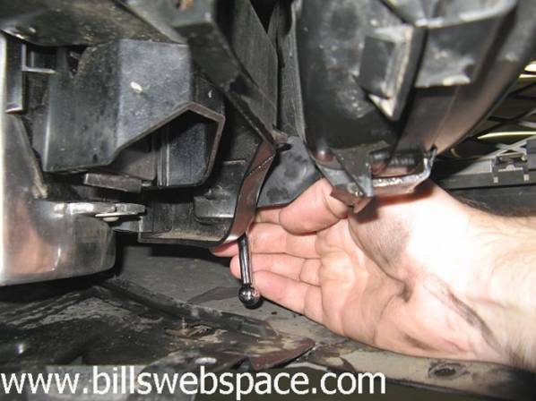
Step 10: Now you must
remove the brake duct vent. You can do this by removing the 8mm bolt located on
the bottom left and side of the air vent. I found it easier to flex the duct and push towards
the front of the car to pull the front tabs out of the retaining holes, it allowed the duct to move a bit for easier access
to the single bolt at the front of the duct with a socket wrench or wrench.
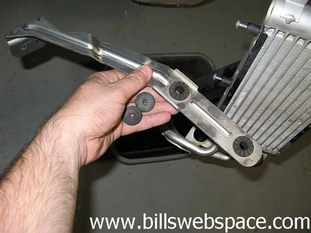
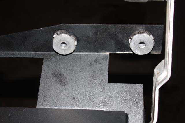
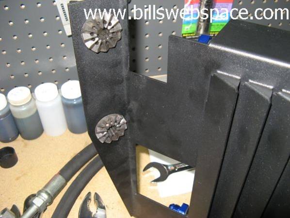
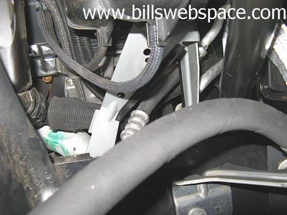
Step11: Using a T20H Torx socket remove
the metal bracket attached to the top of the OEM oil cooler. The cheap bits I bought
broke on the first screw, so I used a pair of pliers on the outside perimeter
of the screw to get the second one out, a little slower but doable if you
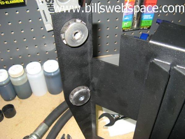
don’t have one of these bits. After removing the screws, you should have
the bracket and two plastic washers.
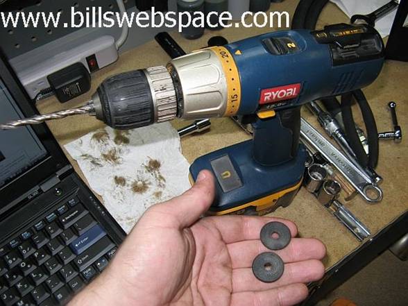
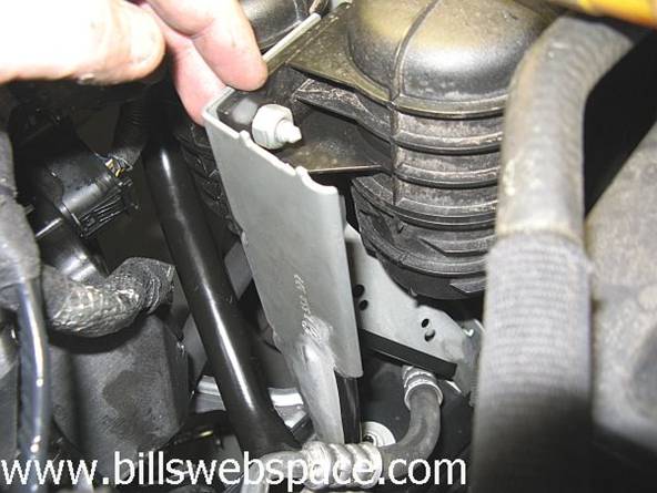
Step 12: Reinstall the bracket,
you just removed to the top of the V K Motorwerks oil cooler with the two 6mm
hex head bolts that came in your kit. The supplied bolts do not work with the OE
plastic washers, I used a ¼” drill bit to
drill out the washers while clamped in a vise.
Step 13: Remove the rubber rings from the
OEM oil cooler and install on your new oil cooler. It is easier to install
these with the metal center section removed.
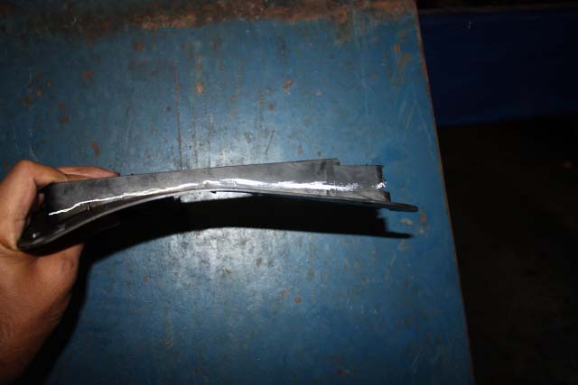
Step 14: Place your brake
duct vent as shown below:
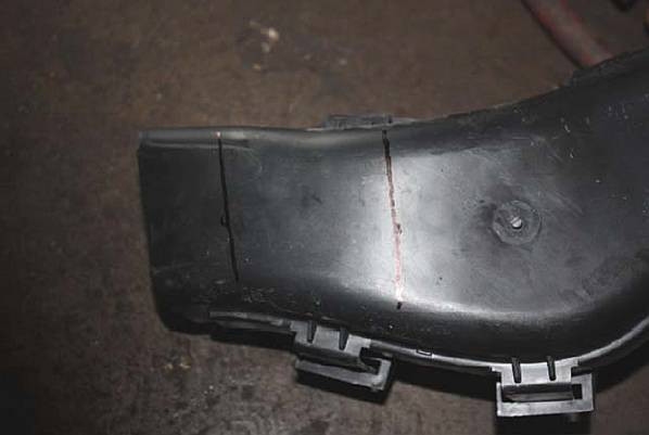
Step 15: From the left edge, measure 1 inch
in and draw a line going perpendicular to the duct. From the same left edge, measure
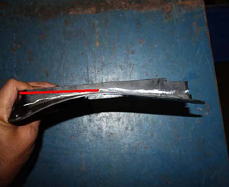
4 inch in and draw a perpendicular line at this spot. It should look like this.
Due to
variances on cars, the 1” and 4” guidelines are close,
I found the 1” mark to be about 3/4” for me after adjusting and the
4” mark to be closer to
3.75”.
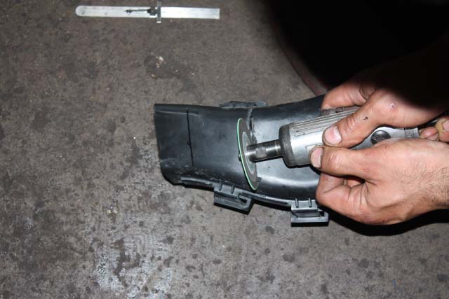
Step
16: Cut
out the area in between the lines. It is hard to see depth in the pictures
provided but I would start out at about 1/4" and cut more if you need to.
I also went ahead and cut ALL the plastic pieces at the same time.
Step 17: After completing step 16, your
brake duct vent should look like the picture shown below. Reinstall the vent by hooking the two rear
locating pins into the holes and then reinstalling the 8mm bolt at the front.
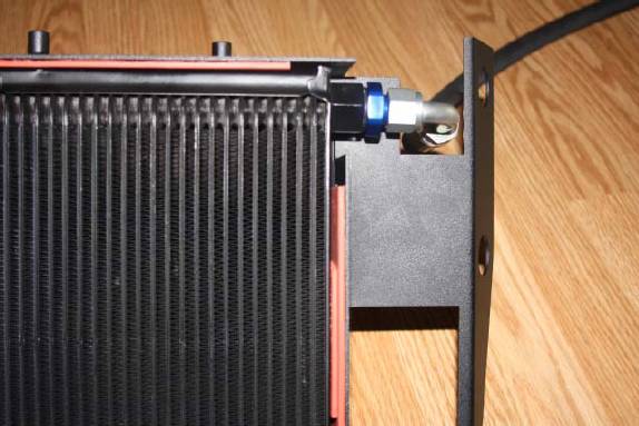
Step 18: By hand, attach the hose with two 90 degree fittings to the
inlet on the top of the V K Motorwerks oil cooler. Attach the straight fitting
to the bottom of the oil cooler. Do not tighten the hoses yet. After trying to do it a
few different ways I found it easier to install the bottom/straight fitting
hose after installing the intercooler; the top/angle fitting HAS to be
installed on the intercooler BEFORE the intercooler is installed.
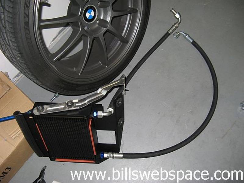
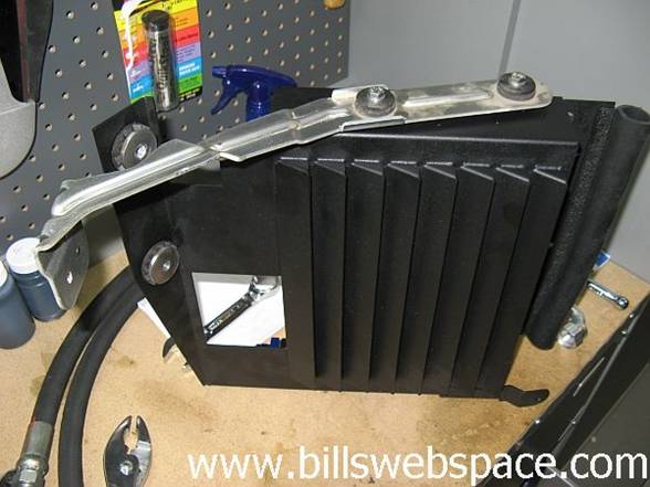
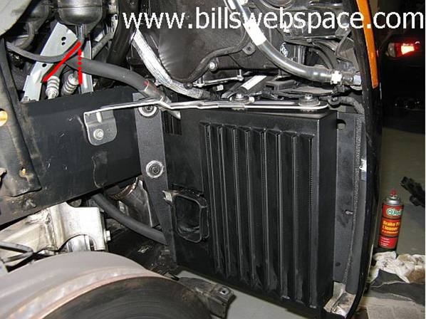
Step 19: Mount the bracket and install the oil cooler to the car.
Once the oil cooler is mounted use a 7/8” stubby wrench to tighten both
of the hose fittings on the oil cooler. This is probably the toughest part of the install because of the tight
space. The
top oil cooler fitting is best accessed from the front using the cutout the
hose passes through, the bottom fitting can be accessed from below and behind-
it IS tight but doable.
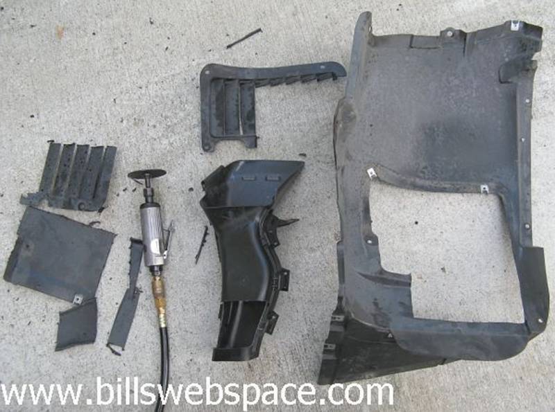
Now, just for kicks,
compare your OEM intercooler to the new one you just installed.
![]()
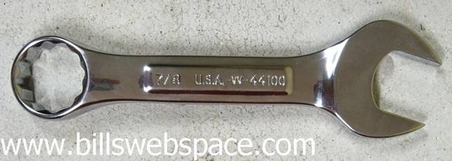 Sears Item# 00944100000-Model#
44100
Sears Item# 00944100000-Model#
44100
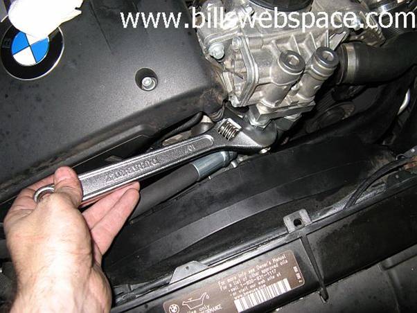
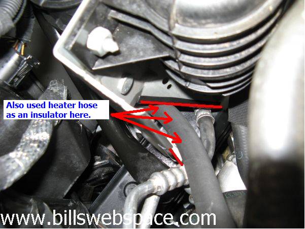
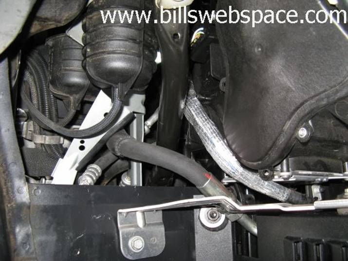
Step 20: Run the lines to the thermostat
adaptor and connect them. Make sure that they are not rubbing up against any
thing that can make them rip. The hose ends on the oil filter thermostat adapter can be
tightened using an adjustable wrench. Also make sure not to over-tighten the hoses. I used a combination of
soft plastic edging on metal edges and plastic conduit and cut heater hose to
make sure the oil cooler hoses would not be rubbing, make contact with, or get
cut on anything. Small adjustments to the angle of the fitting as they are
tightened can make a bit of difference too. I will probably check these hoses
periodically to make sure no rubbing issues exist.
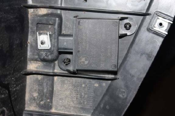
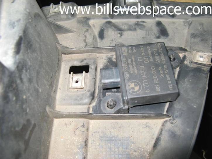
Step 21: Now you will have to relocate your
TPM sensor. To do this you will have to push out the pins in your wheel well
liner. I
used the T20 Torx driver I already had out to push the pins out from the module
side and release the plastic rivets.
Step 22: Place the TPMS as shown in the
picture below and use a 17/64 drill bit to make holes to install the locking
tabs. The
1/4” drill bit I already had out worked fine for this, you will want to
position the TPMS module as close to the edge as possible to avoid interference
with the screw that will be close to the plugged in harness.
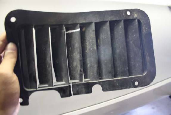
Step 23: Take the OEM oil cooler vent with
the side of the vent that faces into the wheel well count to the third vent fin
from the left. Measure up 5.25 inches from the bottom. Now mark this spot and
cut as shown in the pictures below.
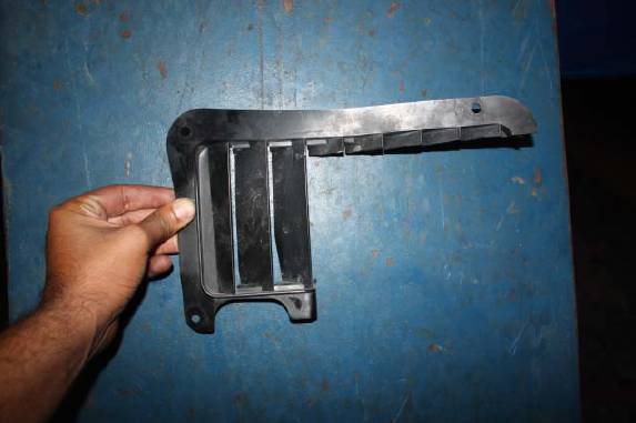
Step 24: Now you will need to cut the backing of that vent:
Mark the top of the vent as shown and cut.
My
cut deviated a little from the suggestion above, noted by the red line where
the suggested cut really did not work because the vent louvers are in the way.
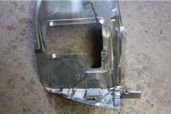
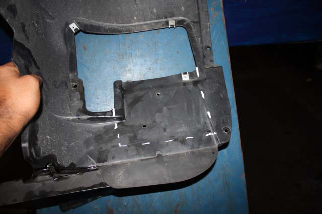
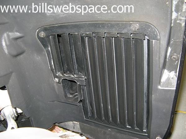
Step 25: Now you have to cut the wheel well
liner. Mark and cut as shown below. Use the left and bolt screw as a reference
point to figure out how far to cut down. I had to move the left edge in the first pic
below out a ¼” to clear the cooler louver, again may vary due to
build variances. I found there were several ridges at the base of the fender
liner that caused clearance issues so I notched them to make them a little more
flat (picture shows what they looked like BEFORE fender liner was cut).

Step 26: Now install the
wheel liner and vent and you should end up with this:
Step 27: Put on the wheel and air intake
piece that you took out. Check your oil level, add if needed. My car was showing about
a ¼ quart low after installation.
Step 28: Enjoy your car!